Attention all registered users. The new forum upgrade requires you to reset your password as you logon for the first time.
To reset your password choose this option that is displayed when you attempted to login with your username: "Forgotten your password? Click here!"
You will be sent an e-mail to the address that is associated with your forum account. Follow the simple directions to reset your password.
If this is your first visit, be sure to
check out the FAQ by clicking the
link above. You may have to register
before you can post: click the register link above to proceed. To start viewing messages,
select the forum that you want to visit from the selection below.
Agree. This was mostly a dig at Kevin in fun. Their tech and electronics ability is light years ahead of mine. This was the most relevant comment I could make about this subject.
When I have a problem, Kevin can usually help me solve it. Thanks for your contributions to the hobby Kevin.
@ Pete - Thanks, I'm just glad I can put a little back in. I've gotten so much out of this hobby and plenty of it has been because others have helped me along the way.
@ Tim - ASCII - LOL.
Since we're already going down hill remember that there are 10 kinds of people in the world.
(Those who do read binary and those who don't.)
Hi Tim:
I've solved the problem. It was the sequence in the reading of the array. I thought that the sequence were 0 to 8. But not, is 8 to 0, and the sync value is 8, not 0. Too, the "Delay" at the end to the sketch. The delay, I don't know the cause, did that some values wasn't readed.
Thanks for your help
Best Regards
Pedro
Hi Tim:
I’ve used Multiswitch a lot of years ago. First an unit of Model Control Devices, in my first transmitter, a Multiplex Europa Sprint. After with Robbe F-14.
I used them for open and close valves: dive, surface, periscopes, torpedos, lights, sounds…
When I began to built my Akula-II, with a methanol engine and snorkel (not finished yet), I look that I need do controls that my radio with Multiswitch cannot do. I needed a microprocessor.
When I built my Ictineo-II, I began to learn Arduino, and now it run with Multiswitch + Arduino, but is a very complex system, because need a lot of relays to transform 12V signals from Multiswitch to digital imputs to Arduino. I can’t use 5 volts in multiswitch because some outputs from multiswitch I use to direct devices: Smoke generator, Sounds, lights, thrusters… and Robbe multiswitch don't support two different voltage feedings.
By the way, I found an alternative to Robbe multiswitchs, from http://www.cp-elektroniks.de
Claus has a lot of devices, with more functionalities than Robbe units, more cheeper, two feedings, selective memories, leds in each output, calibration, and light gadgets included in the 16Multiswitch, and alternative for all transmitters, like Robbe and Graupner.
Claus answer in english, and Paypal payment method. He is very friendly.
In the Ictineo, Multiswitch On-Off this functions]http://www.subcommittee.com/forum/icon_biggrin.gif[/img]
In other ships]http://www.subcommittee.com/forum/icon_biggrin.gif[/img]
pedro contacted me a few days ago telling me he was still having problems getting his arduino code to work the way he wanted to, so he took the code i pasted here, and tried to get it to work, but couldn't. i decided that was a perfect excuse to revisit this, now that my FC28 is back from the repairs (and has been for over a year). this code is not that complicated, but it is VERY different than the original code i posted, and as an extra added bonus, i gave it something to actually do. I bought one of these, quite a while ago, specifically for this purpose, thinking i could hook up two multiprop encoders to my FC28, and drive 16 servos with it...
You want to make a cool robot, maybe a hexapod walker, or maybe just a piece of art with a lot of moving parts. Or maybe you want to drive a lot of LEDs with precise PWM output. Then you ...
it will allow a single simple arduino to operate up to 16 standard r/c servos. exactly what i need to decode two multiprop channels worth of data. the code i am posting here will only handle one channel currently. I have commented the sketch to indicate where you can ignore the code specific to the servo driver.
the code basically consists of three functions: setup, loop, and calcServo, and requires three connections to the receiver - GND, 5v, servo signal. as it is written, the signal wire from the receiver goes to pin 10 on the arduino.
additionally, i have four wires going to the servo driver.
finally, i have a couple pictures of the setup, and a youtube video of the dingus operating.
Code:
#include <Wire.h>
#include <PinChangeInt.h>
// next line is optional
#include <Adafruit_PWMServoDriver.h>

#define SERVO_IN_PIN 10
volatile unsigned long ulServoInShared= 0;
volatile unsigned long ulServoStart = 0;
volatile int multi_servo[17];
volatile int current_servo = 0;

//next three lines are optional
// flag to indicate the i2c servo driver is attached
Adafruit_PWMServoDriver pwm = Adafruit_PWMServoDriver();
boolean servos_exist = false;

void setup() {
  byte error, address;

  Serial.begin(9600); // other values include 9600, 14400, 57600 etc.

  // set up interrupt for receiver input
  PCintPort::attachInterrupt(SERVO_IN_PIN, calcServo, CHANGE);


  //from here to "end optional" comment is optional
  address = 0x40;  // i2c address for servo driver
  // check to see if i2c device exists
  Wire.begin();
  Wire.beginTransmission(address);
  error = Wire.endTransmission();

  //device exists
  if (error == 0)
  {
    Serial.print("I2C device found at address ");
    Serial.println(address);

    servos_exist = true;

    pwm.begin();

    pwm.setPWMFreq(60);  // Analog servos run at ~60 Hz updates

	//set the default values for all 16 servos - 366 = mid range of driver for servo (1500)
	//driver is kind of odd... values range from 0 to 1000
	// which represent 0 milliseconds to 4096 milliseconds long pulse.
	// we want a min pulse of 1000, mid of 1500, max of 2000 milliseconds
	// that equates to a min val of 244, mid of 366, max of 488
    uint8_t servonum = 0;
    for (servonum = 0; servonum < 16; servonum++) {
      pwm.setPWM(servonum, 0, 366);
      multi_servo[servonum] = 1500;
    }
  }
  //end optional
}

void loop() {
  int servonum = 0;
  int servoval = 360;
  float tempval = 360.0;

  // array slot zero is sync - 1 thru 9 are valid servo pulses
  for (servonum = 1; servonum < 9; servonum++) {
    //from here to "end optional" comment is optional
    if (servos_exist == true) {
	  // convert from rx level to driver level
	  tempval = multi_servo[servonum];
	  tempval = tempval * 0.244140625;
	  servoval = round(tempval);
	  // want to use servo slots 0 to 8
	  pwm.setPWM(servonum-1, 0, servoval);
    }
    // end optional

    Serial.print("Servo: ");
    Serial.print(servonum);
    Serial.print(", ");
    Serial.println(multi_servo[servonum]);
  }
}


void calcServo()
{
  if (digitalRead(SERVO_IN_PIN) == HIGH)
  {
    ulServoStart = micros();
  }
  else
  {
    ulServoInShared = (uint16_t)(micros() - ulServoStart);
    current_servo++;

    if (ulServoInShared < 1000) {
      current_servo = 0;
    }

    if (ulServoInShared > 2000) {
      current_servo = 0;
    }

    if (current_servo < 10) {
      multi_servo[current_servo] = ulServoInShared;
    }
  }
}
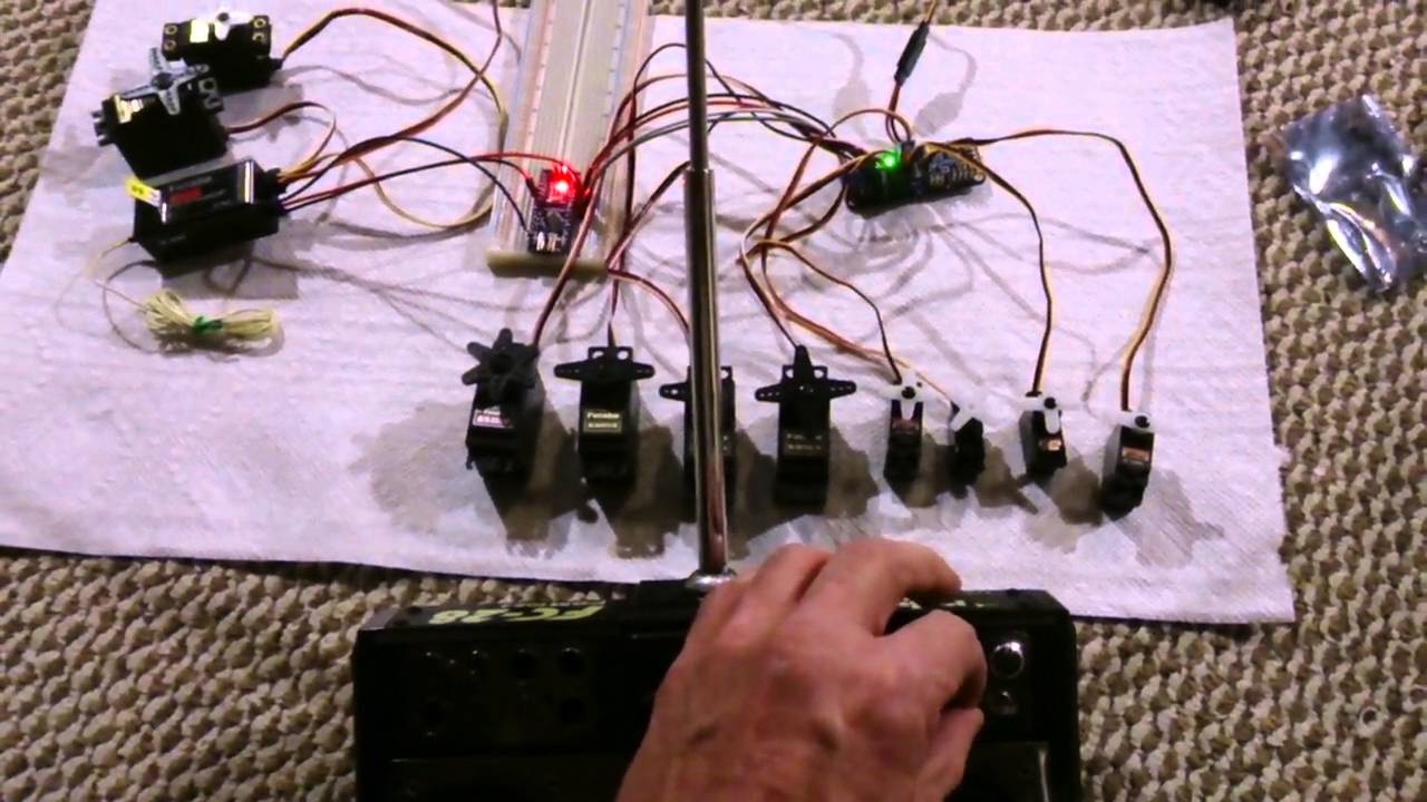
First should be the Robbe FC-28 with the multi-prop encoder in the upper right side bay, it has 8 controls: four rotary knobs, three 3-position switches, and one 3-position momentary switch.
Second is the actual receiver side of the setup. On the left is the receiver with two servos in channel 1 and 2, a BEC plugged into channel 3, and the pins to the arduino in channel 7. the three pins connect to pin 10, 5v and GND on the arduino.
next we have the arduino, which runs the servo driver. there are four wires going to the servo driver from the arduino, SDA, SCL, 5v & GND. this powers and controls the logic side of the driver. at the top of the driver is a connection to another BEC which is feeding power to the servos. at the bottom of the picture on the right side are the eight servos, grouped in sets of four, the four rotary knob controlled servos, and the four 3-position switch controlled servos.
and the youtube video of the dingus doing its thing:
basically, using a $6 arduino, and a $15 dollar servo driver, i have reconstructed the $125 robbe decoder that you can no longer find in stock at european hobby shop websites.
i am not 100% happy with the functionality of the $15 servo driver, it is kind of choppy with the proportional servos. i might try an $18 servo driver from pololu.com, and see if it works better.
of course, if you plan on doing something else with the decoded data, then the servo driver is un-necessary, and you get to write the code to handle that.
in order to get this working 100% of the time, on a variety of arduinos (arduino nano, arduino micro, and sparkfun pro micro) i have had to use pin-change interrupts, and move all the decoding of the servo signal to the interrupt code. using the technique in my first version of the code, the arduino would occasionally miss sync signals, so i had to do all this in the interrupt. to do that, i had to reduce that code to its bare bones. all the smarts to this sketch are now in the "calcServo" function.
the logical elements of the setup function are all still there, but there is very little for the loop function to do, it simply takes the array of values for the servo positions and sends them to the driver.


Comment