Attention all registered users. The new forum upgrade requires you to reset your password as you logon for the first time.
To reset your password choose this option that is displayed when you attempted to login with your username: "Forgotten your password? Click here!"
You will be sent an e-mail to the address that is associated with your forum account. Follow the simple directions to reset your password.
If this is your first visit, be sure to
check out the FAQ by clicking the
link above. You may have to register
before you can post: click the register link above to proceed. To start viewing messages,
select the forum that you want to visit from the selection below.
Tim Tim Tim...you silly cone. Who says I was talking about the La class? Trust me there were other boats with such thing as the WAA and even electronic optical scopes. Remember everything you see was tried out on some spook op boat at one time or another. Maybe a dunk in the Thames will make you a bit saltier?
I can tell you the names of the boats that had non-hull penetrating scopes, I have seen them with my own eyes. They were being tested when you were still in high school and during the time that was doing cold war patrols.........
I take it the dip in the Thames was effective? Do you feel better now? Still wrong Poor cone. How far back do you think those scopes go Tim? On second hand were off topic again.
We can talk about that in person........better that way.
Joel,
Some info for you for when you do flood grates. The Seawolves didn"t have grates per say, they have flood holes.. Each are about 4 and a half inches in diamter and have varying patterns based on the size of the plate they are drilled into. typically a 3x4x6, 4x3x7, 4x5x7, or 5x4x6. What I mean by that is that the leading row of holes on the plate has 3 holes, next line is 4 holes, and there are 6 lines, etc, etc. and each line is offset meaning that the holes in the next line are between 2 holes in the previous line.
Those didn't post like i wanted, shift the three 0's in 1/2 space and you get the pattern. Substitute the other numbers of holes and lines and you get the drift
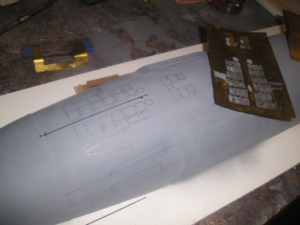
Alright, now we’re getting into the fine detailing part of the project. In order to do this detailing I need stencils for scribing and I have quite a few for basic shapes, but I need some that represent Seawolf specific shapes, like hatches and torpedo shutters. So to get these custom shapes the best resource at my disposal is the process of chemical milling (aka photoetch). For those that have followed my worked since the beginning with my USS Permit they will notice that the quality of my “milling†work has improved ten-fold from that time. The reason for this isn’t fluke but hard work and perseverance...lots of practice, screw ups, experimenting, new equipment and materials, new techniques, and lots of research. Anyways, I’m using this stuff not only for stencilling, but for actual adhere-on details as well to my plug. For those worried that my usual fibreglass hull mould won’t be able to take that much detail, fear not as my plan this time is to go with rubber-glass hybrid moulds.
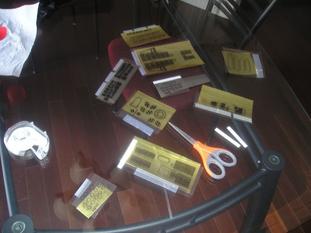
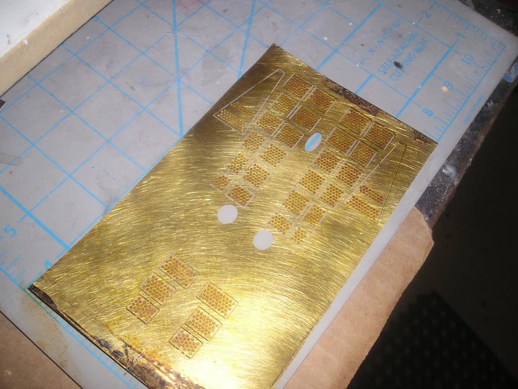
Here’s all my “artwork†for the shapes printed out on transparent film
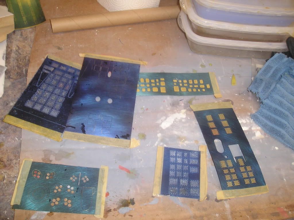
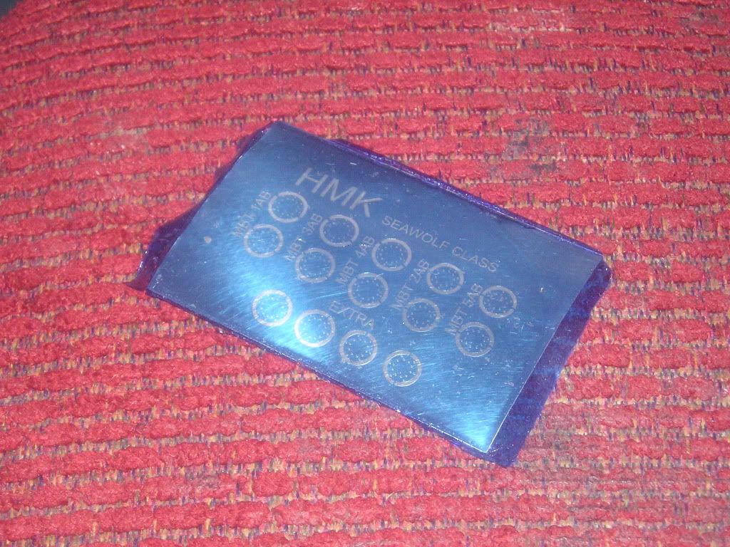
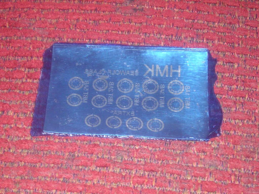
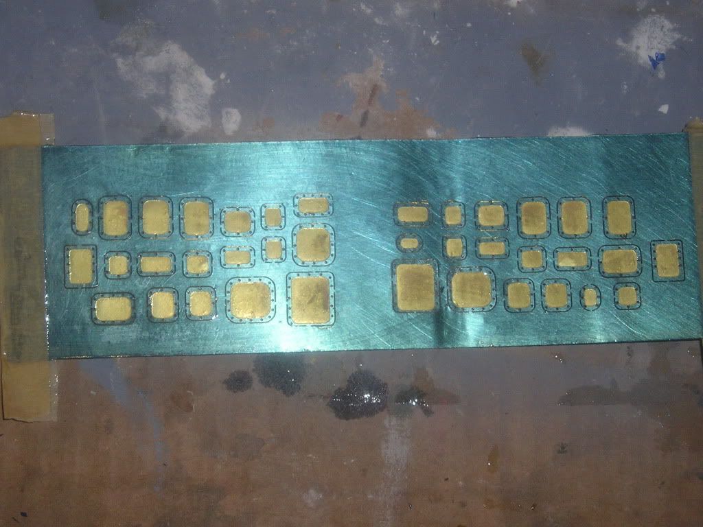
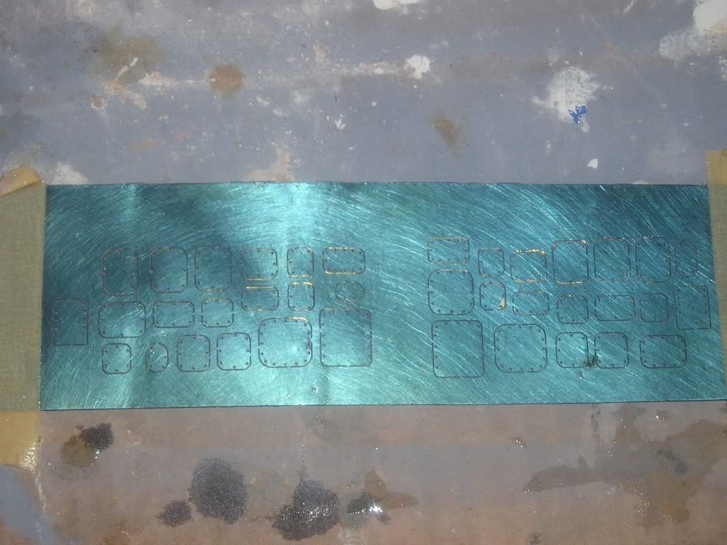
Laminated and developed brass and stainless steel. If you look closely at my HMK ss ballast vent sheet I am using a mix between two sided and one sided art. This gives the effect of only partially etching through the sheet were desired to give a sort of scribe mark. This has been used extensively this time ‘round
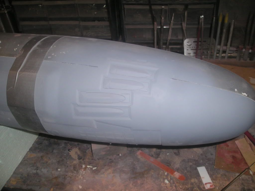
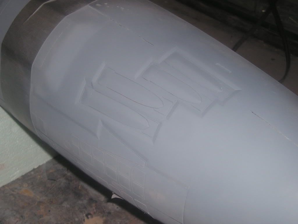
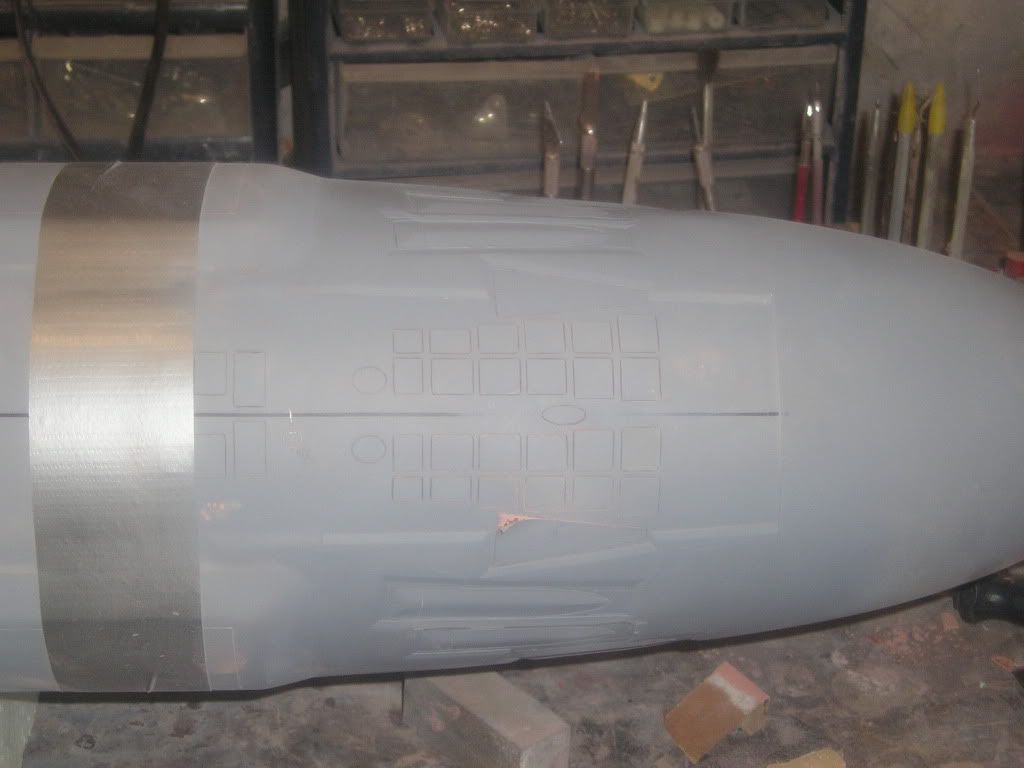
This is a dual purpose sheet. It’s used first as a scribe template, then the grates are glued on between scribe lines...a perfect fit!
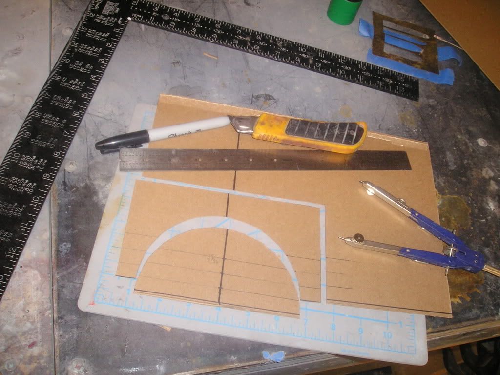
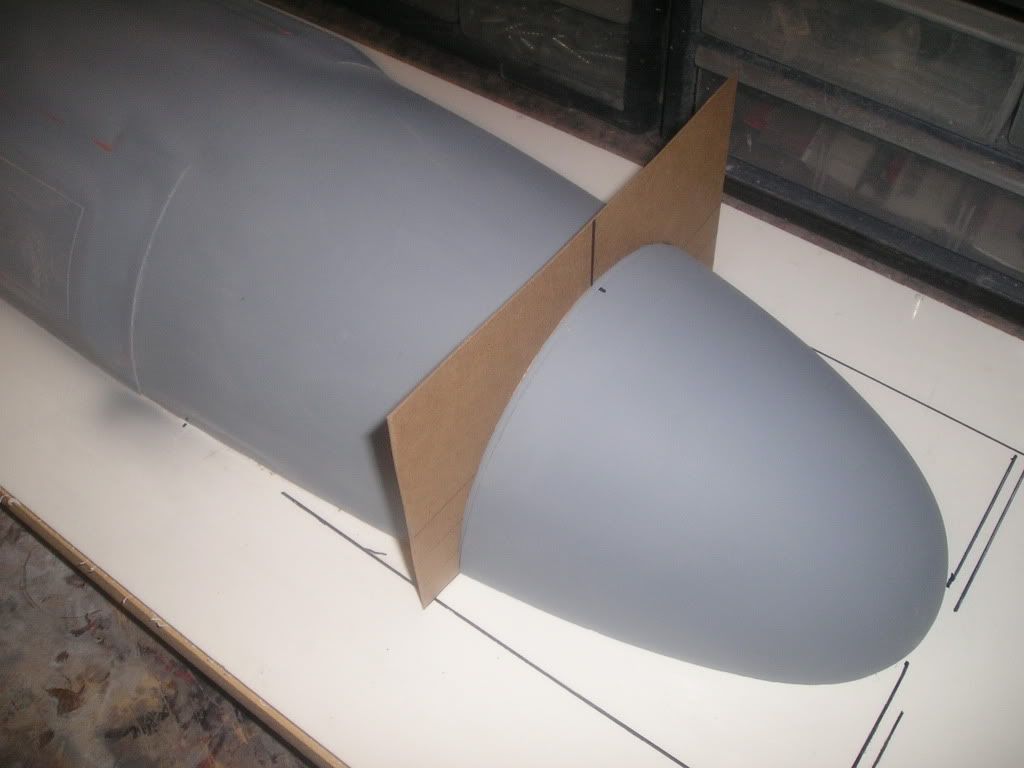
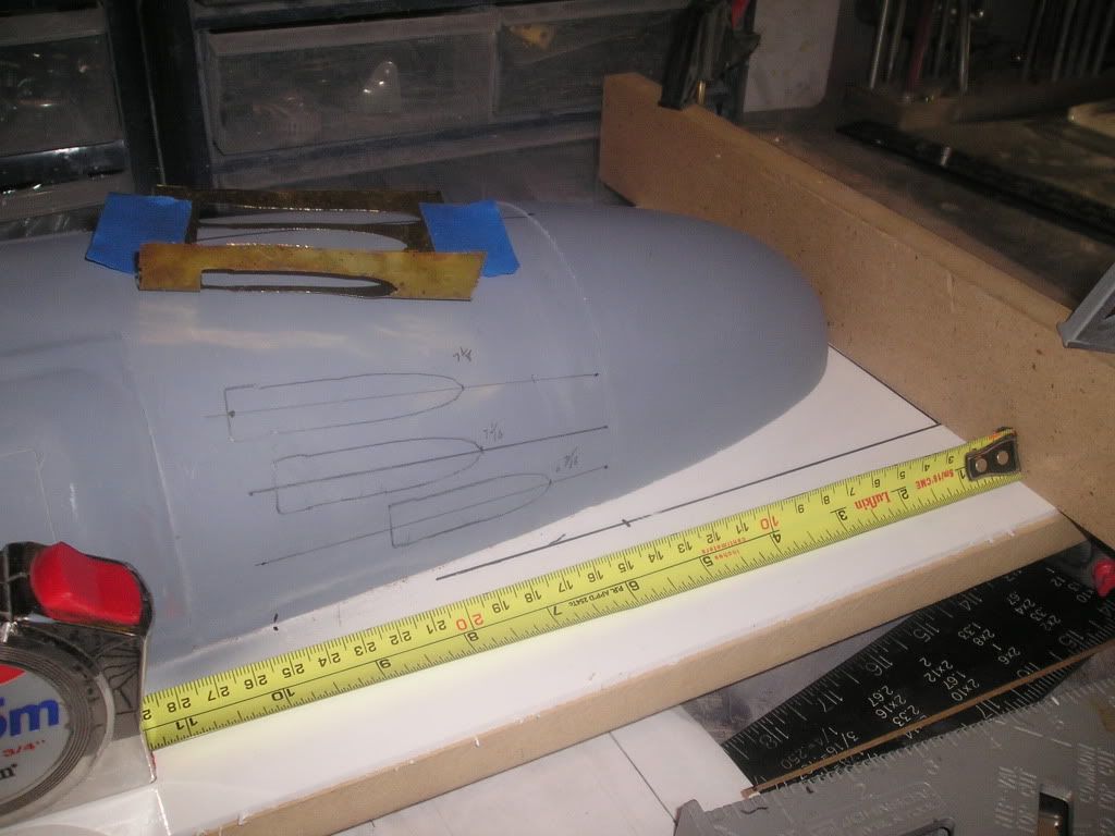
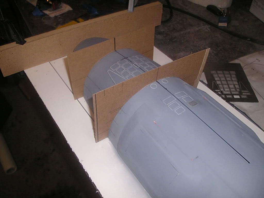
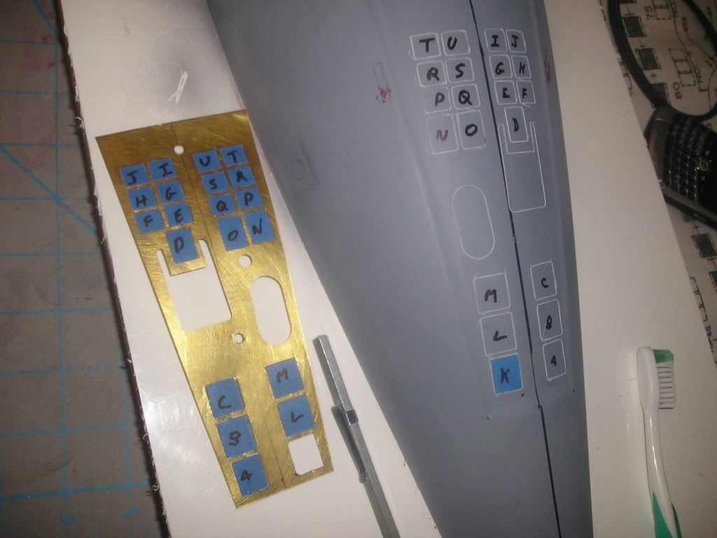
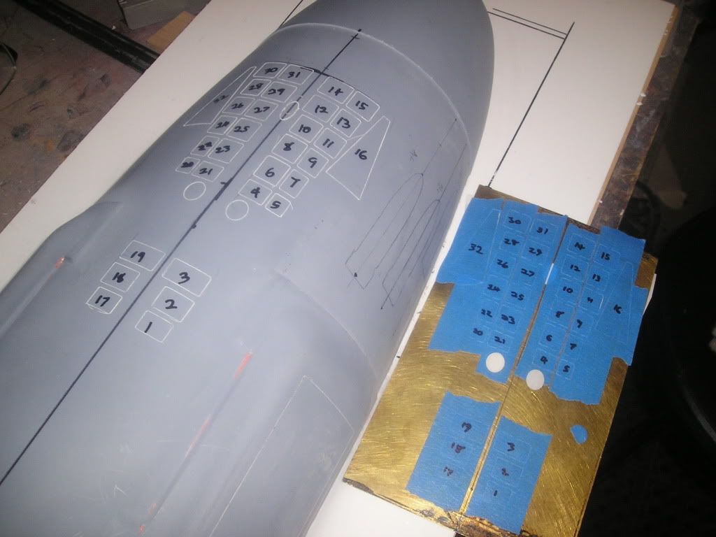
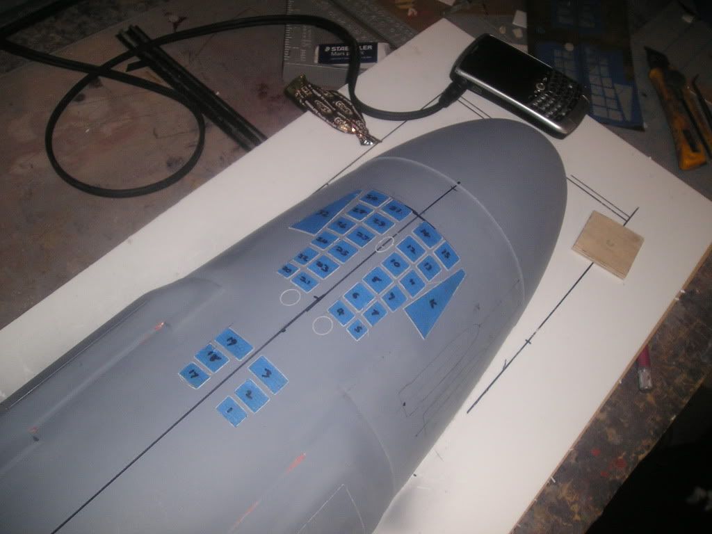
Now, to transfer measurements easily from my plans to the hull using cereal box cutouts
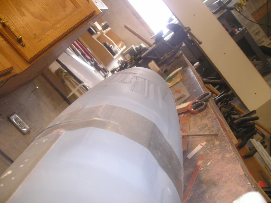
Using my cardboard circle jigs I now have an easy way to transfer measurements from my prints to my hull of revolution. This also gives me an easy way to re-mark my dead center line which runs the entire length of the hull as priming and sanding sometimes can eliminate the original line.
A long straight edge was held against the long side of the hull and a line is marked. I’ll put a square along the line and align the perpendicular arm against the front tip of the hull, mark that line off and I now have my front reference line in which I can clamp a piece of wood to. I can now butt my tape measure against that wood for my length-wise measurements
All lines are drawn out in pencil first...
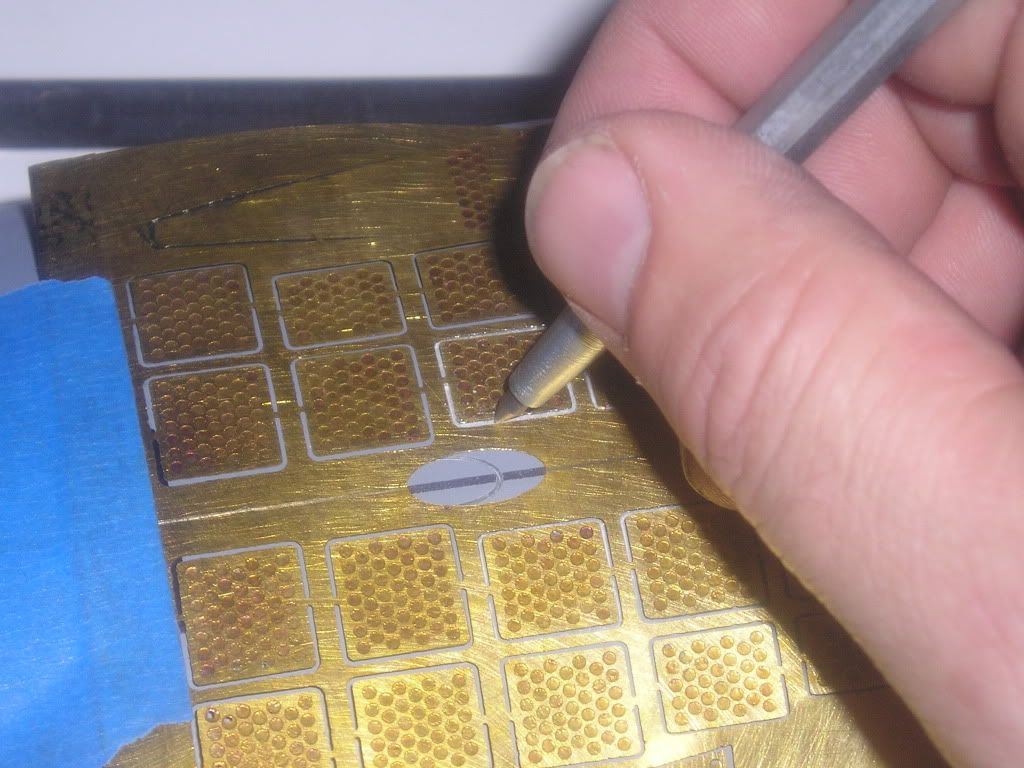
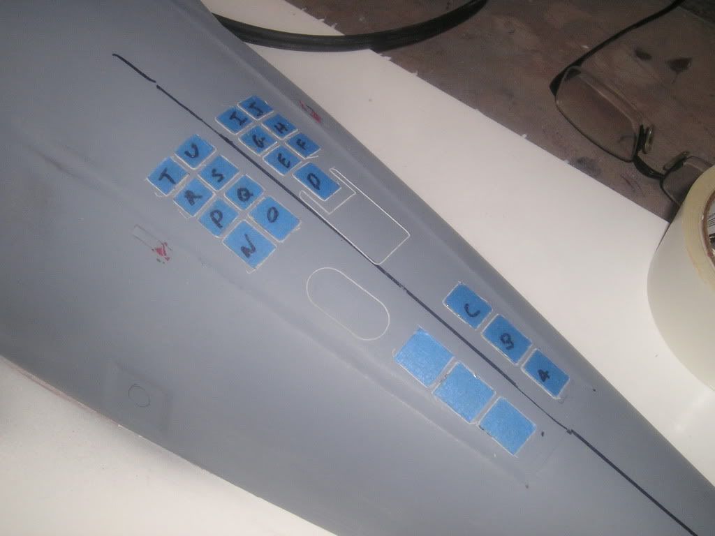
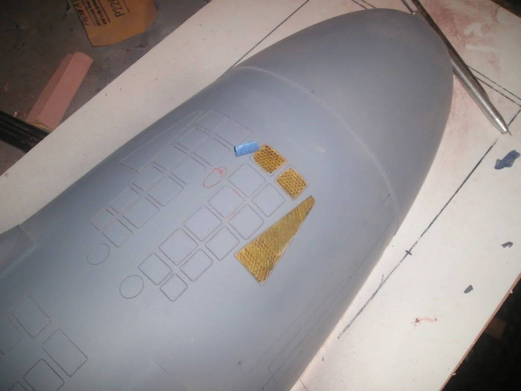
Now I can get down and dirty by using my grating photo etch set as a scribe template. I designed this set so that my scriber point would only fit in the line between the art and the metal that holds it in place.
The photo etch parts that are to be adhered to the hull are covered with tape and cut to shape from the other side of the metal sheet. This tape will not be removed until I’m almost ready to mould the hull. Its function is to protect the subtle etch art from sanding and primer over spray.
Double sided carpet tape is adhered to the back of the sheet and once again is cut from the other side.
Now I carefully cut the art pieces from the sheet, remove the sticky tape barrier and carefully place the part in its scribe mark on the hull
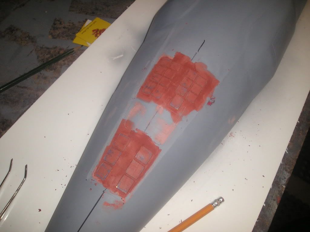
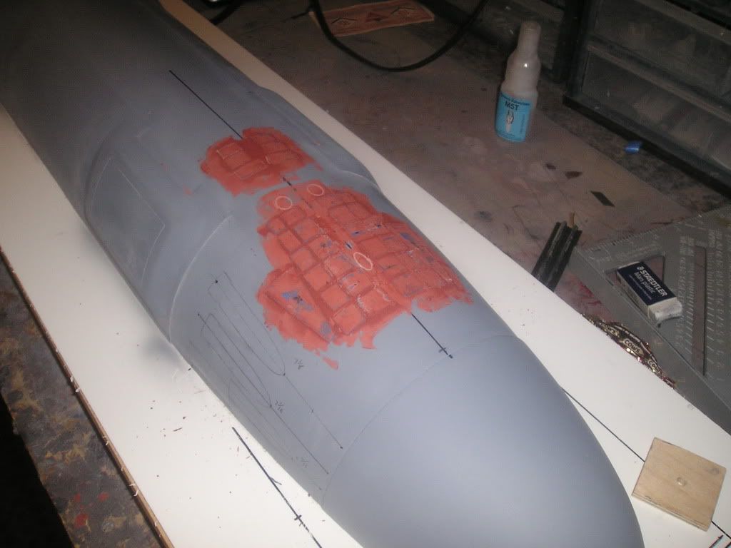
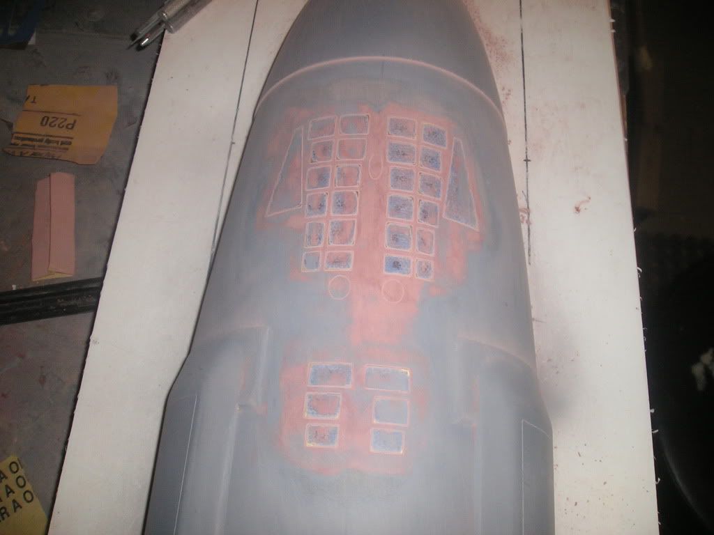
The spaces between the parts are filled with red putty and the lines are re-scribed against the parts. The putty dries, is sanded flush, primer applied and the work is then repeatedly cleaned up by repeating the process.
Here’s a little glimpse as to give the general idea of what I’m trying to do here. The tape will be re-applied...
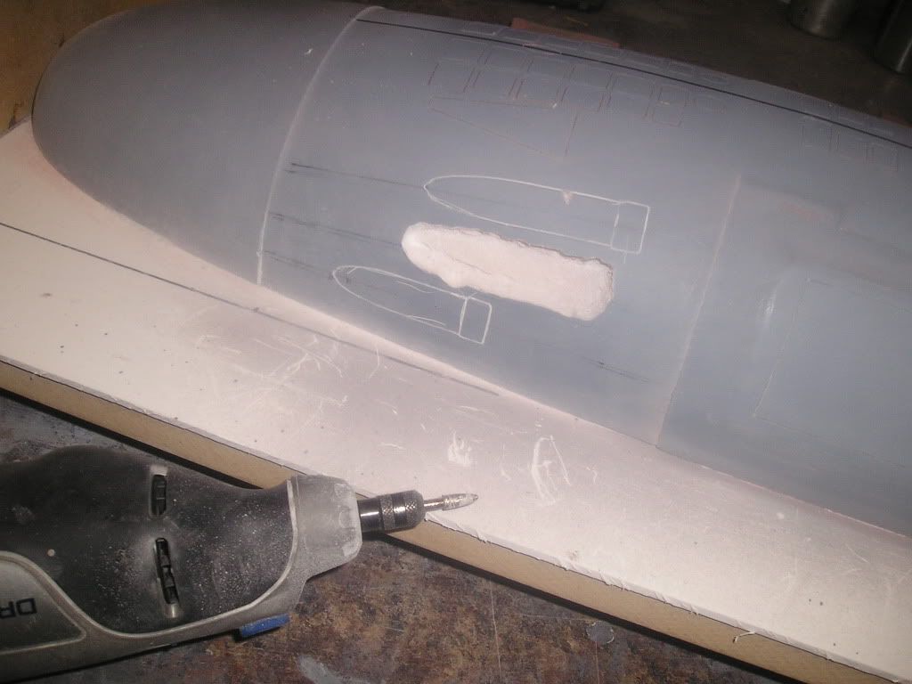
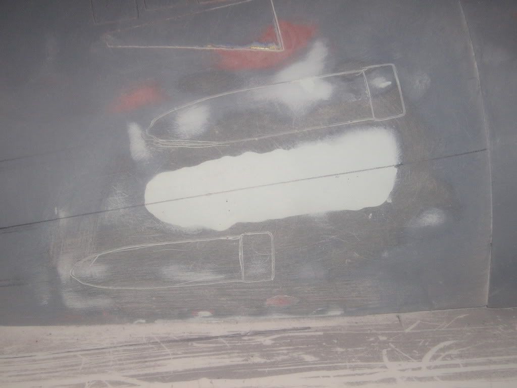
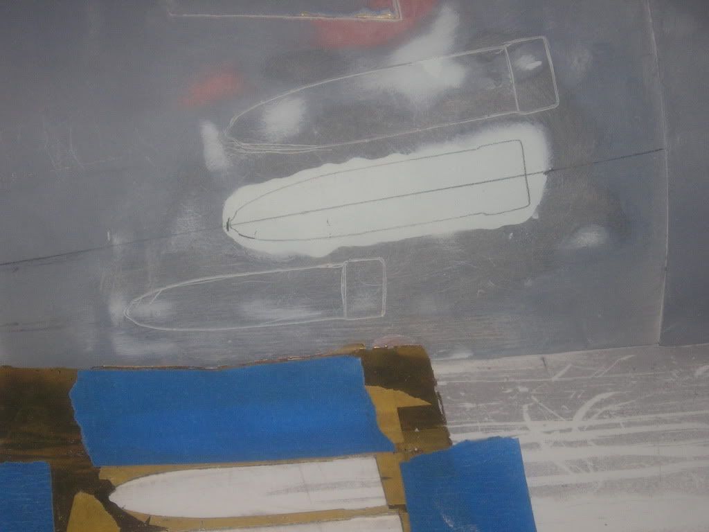
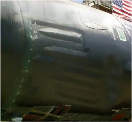
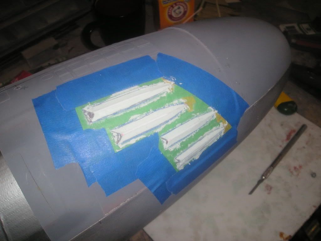
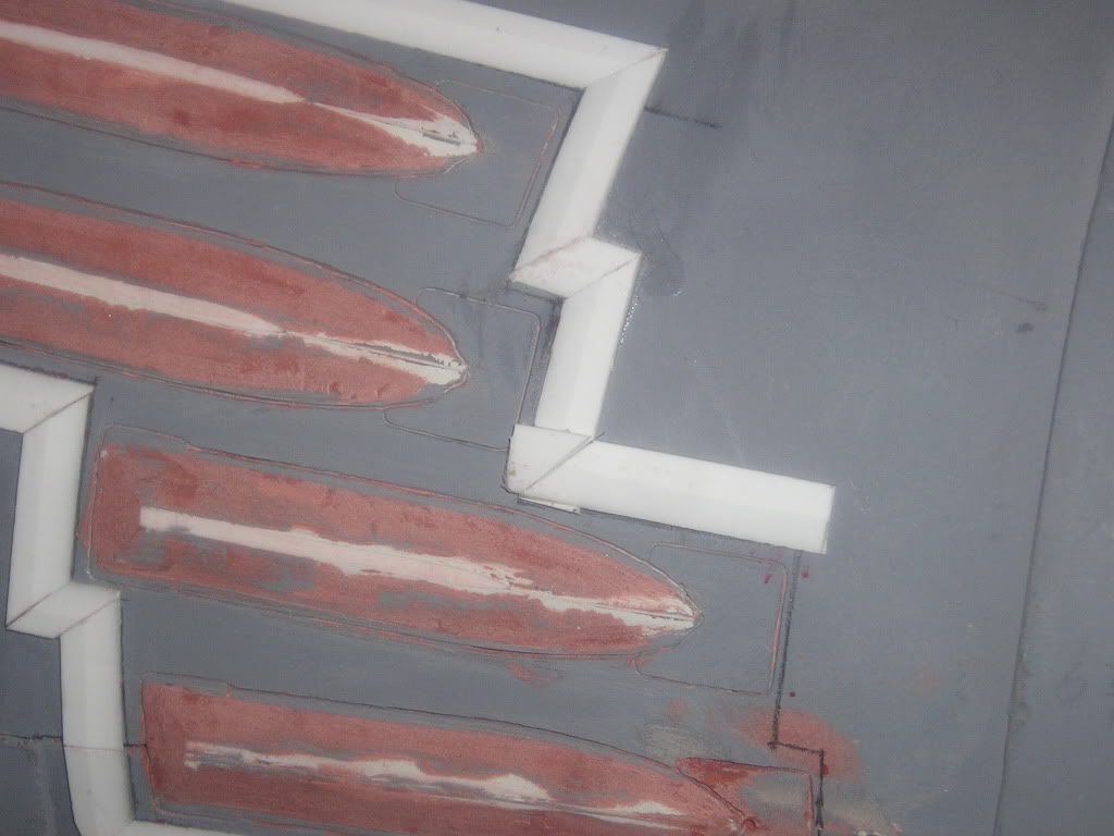
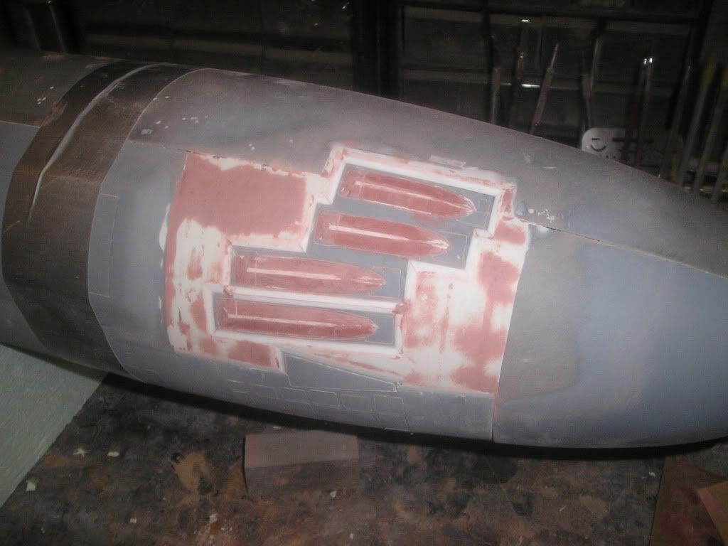
Now onto scribing the torp shutters. As you can see here, things don’t look so good and part of the reason for this is from all the pinholes that are just below the surface on my plug mould. Pure 100% total s**t to scribe into on this area of the sub. Because I didn’t fibreglass under this coating it’s easy to simply Dremel out the crap material and then fill with Evercoat. This has been done extensively throughout this hull. Again I have paid the price in time for not going out and buying a proper spray-on mould surfacing primer. No big deal though, the most important part of the process is to dig out a large enough area to encompass the whole shape being scribed as to give myself a consistent material to run my tool through. Digging through a hard surface and then hitting a soft one doesn’t produce pretty results! I also feel like a dentist!
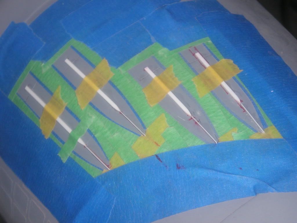
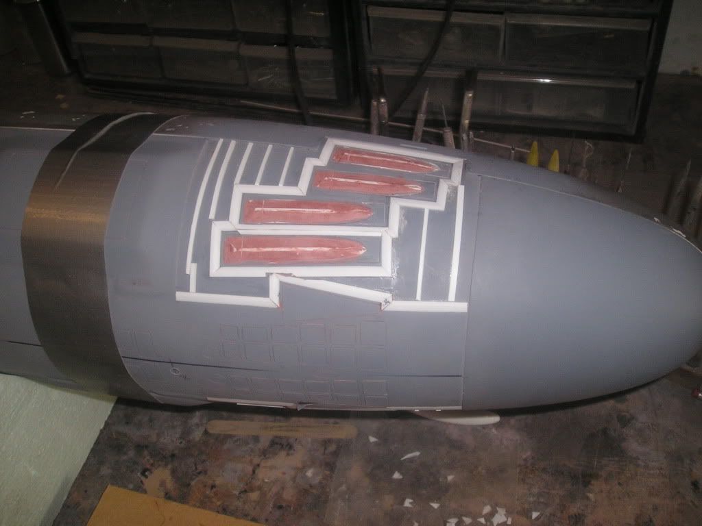
So, going on with the shutters, my objective is to reproduce the raised bevelling of rubber coating that can be found on the real boats. The general desired shapes were taped off and filler was applied in the spaces between tape and styrene middle strips. A sharp razor was run through the semi-cured filler using the edge of the tape and the top of the styrene strips as a guide. Next, red filler was applied to get a better shape. I found that I didn’t really need the tape to do this process properly though...
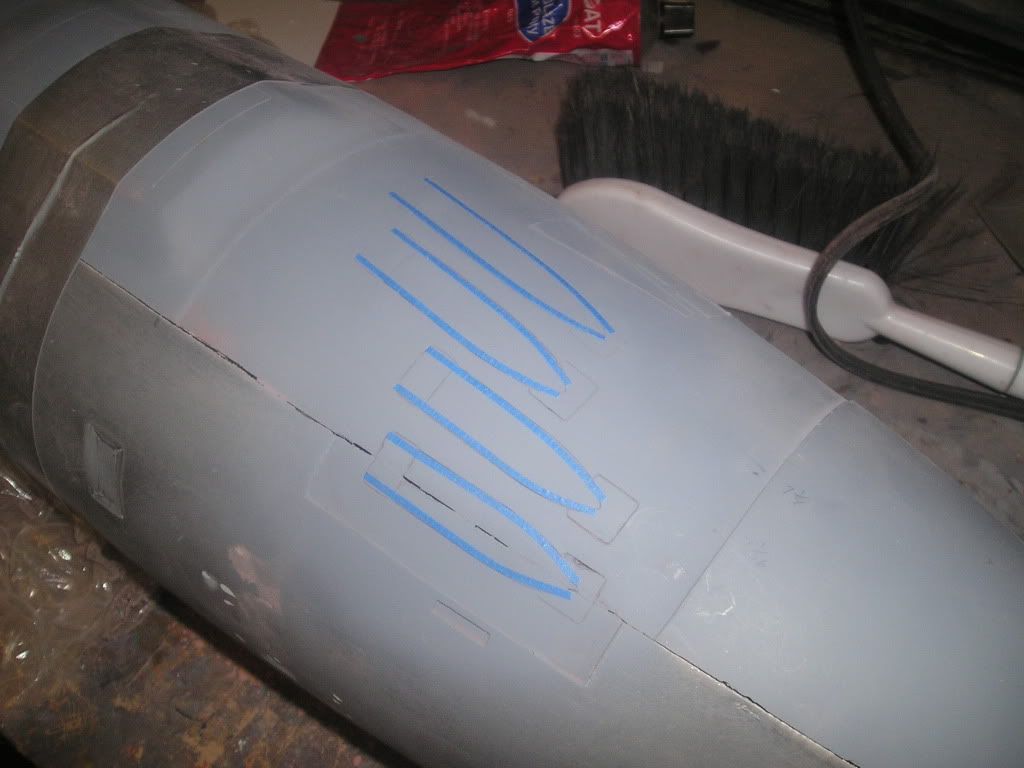
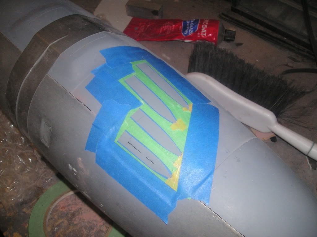
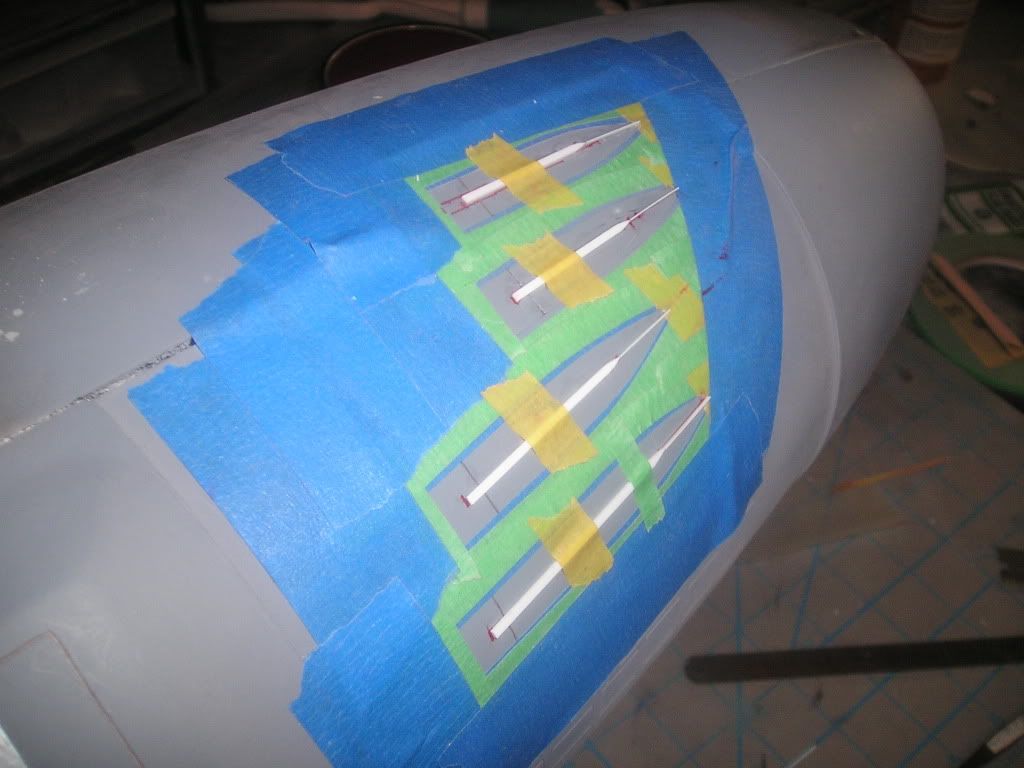
To represent the bevelling around the torpedo tubes here’s what I did:
All that styrene bevelling that I made awhile ago - is now about to come into play. The first step is to mark out where the bevelling is to go. Then you start by sticking your first piece anywhere you want really as long as it’s long enough to accept joints with adjoining pieces. The best example of this I can give is finishing carpentry when mitring all the joints of your trim or door casings. This application has funky angles – none of which are purely 45 or 90 degrees, so it really isn’t practical to use a mitre box. All I do is overlap the next strip of styrene at the joint and then press my ultra sharp hobby chisel (aligned at the intersecting corners) through both pieces and voila! Almost a perfect joint of whatever crazy angle it is.
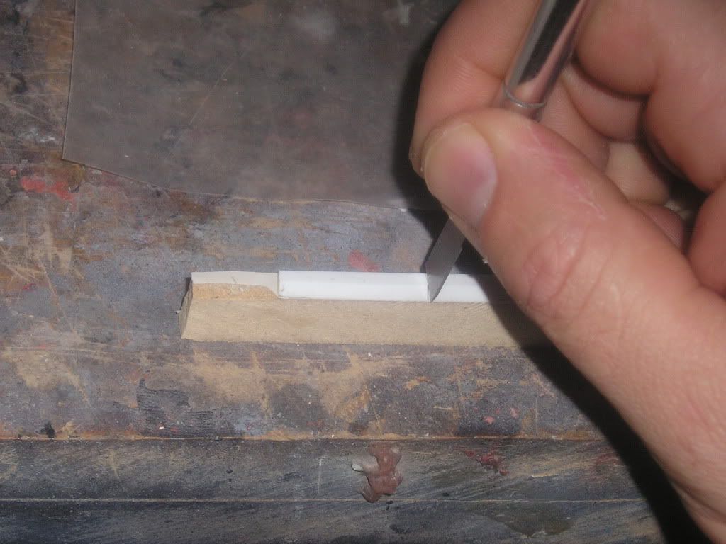
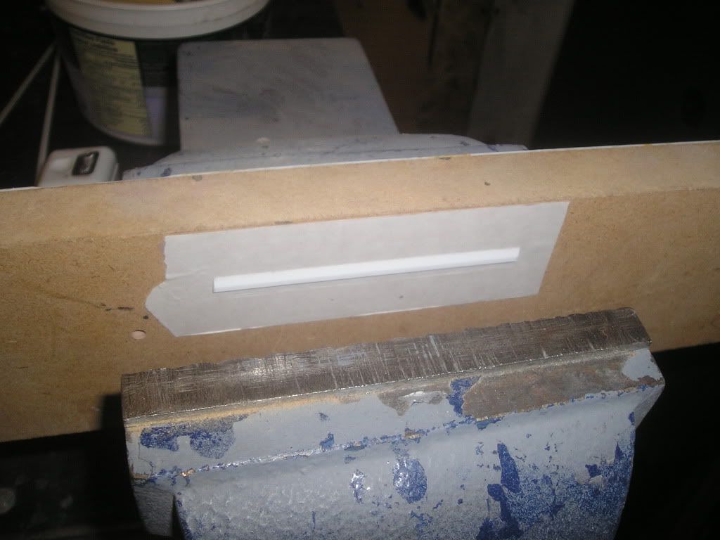
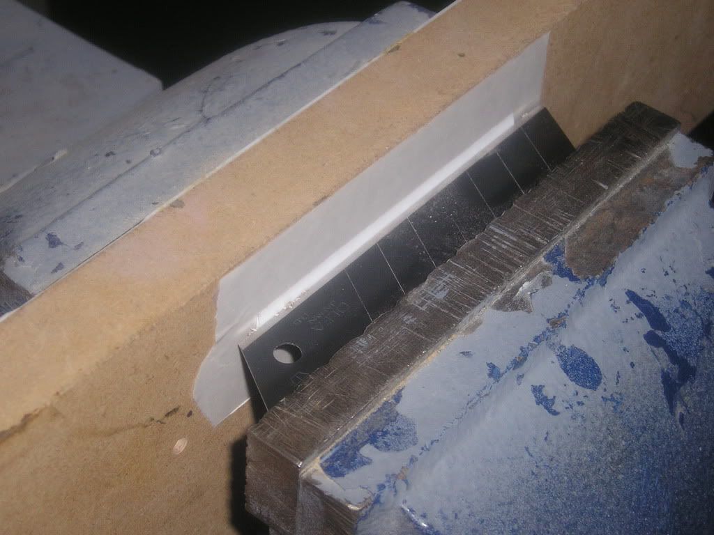
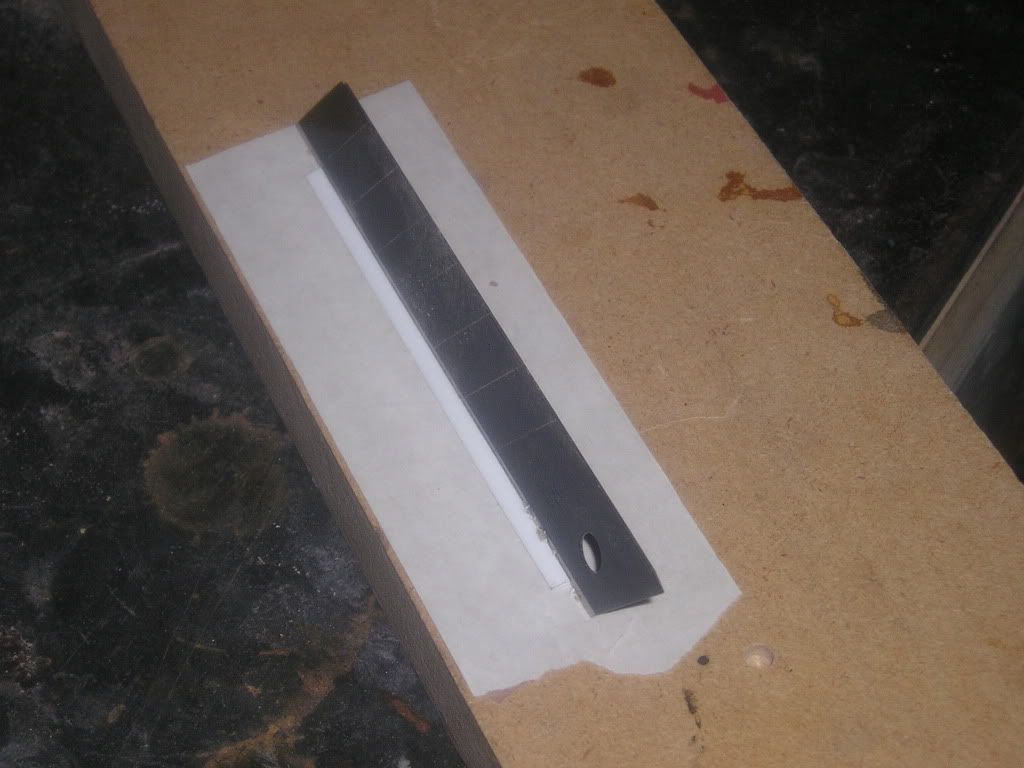
Sometimes I needed just the angled part of the styrene strip due to it being too close to another strip or in the case between the bottom two shutters on both sides I had very little room to work with, period. To cut this bevel cleanly I stuck a length on piece of wood, put it against one jaw in my vise and then carefully place an Olfa knife between it and the other jaw. Patience is needed here to carefully line up the cut, but when everything was snugged up I could then put pressure on the vise and make a nice sweet clean cut. For those reading this I can’t stress enough to be careful with these knives...if not used properly many bad things can happen, and not little things. I’ve seen electricians almost cut clean through their palms of their hands or end up with the blade in their thigh because they had too much blade out and it broke or they were using wrong technique and not cutting away from themselves!
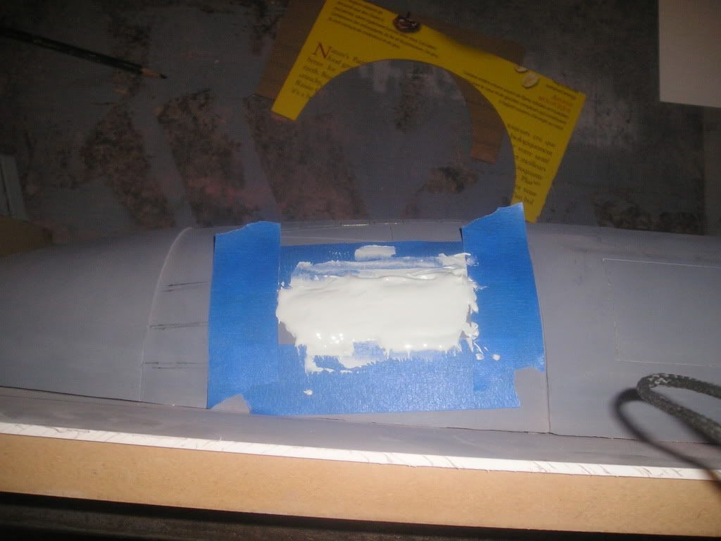
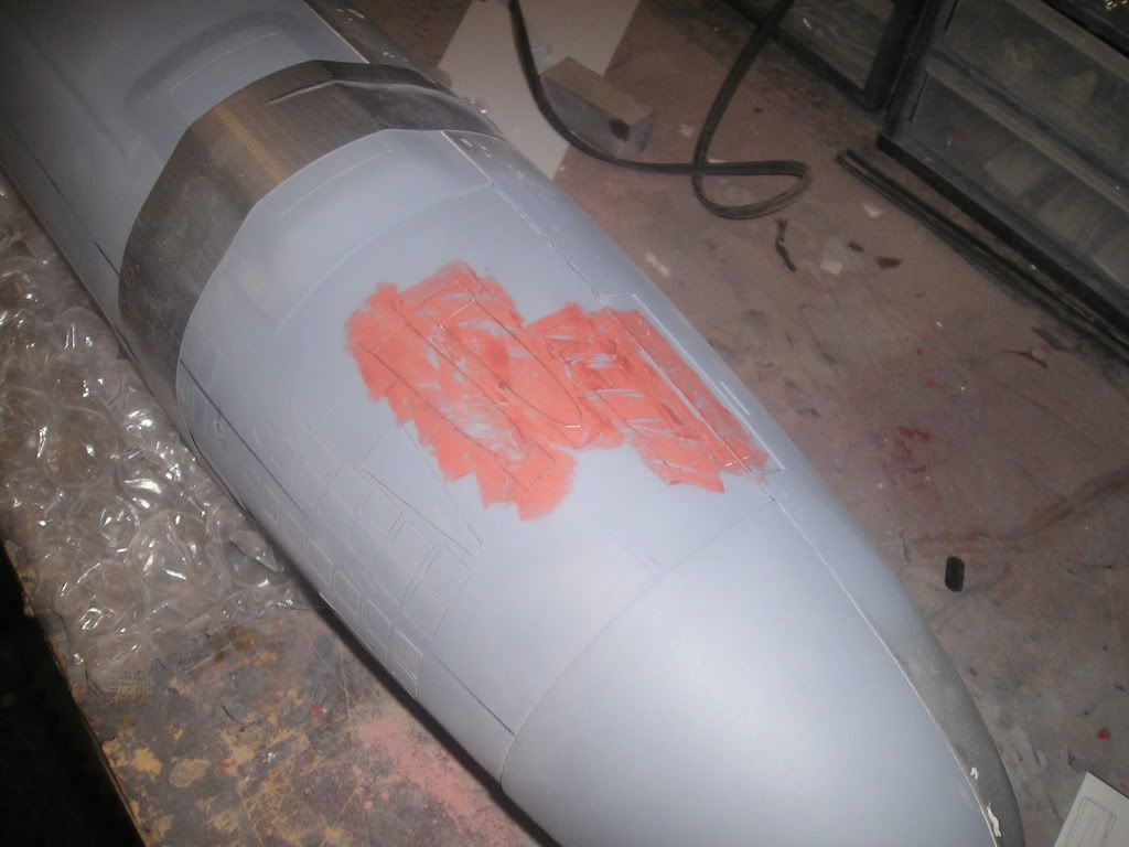
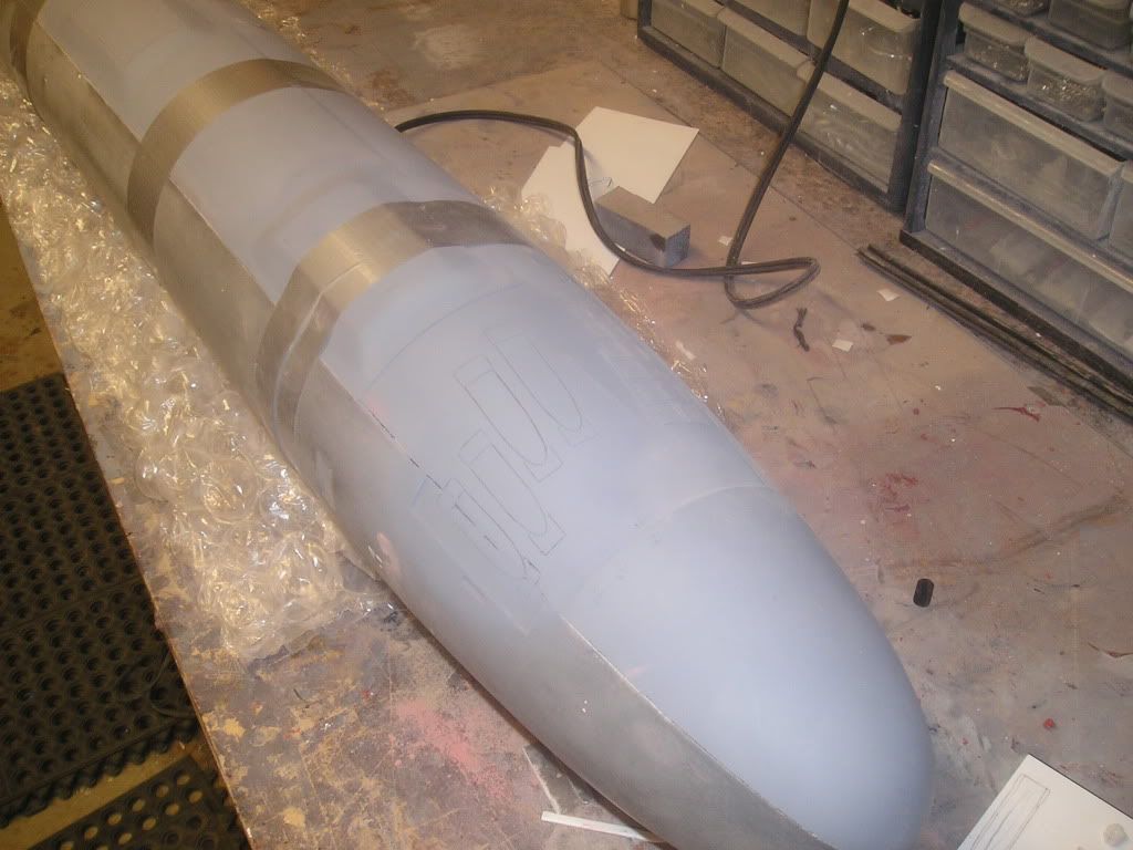
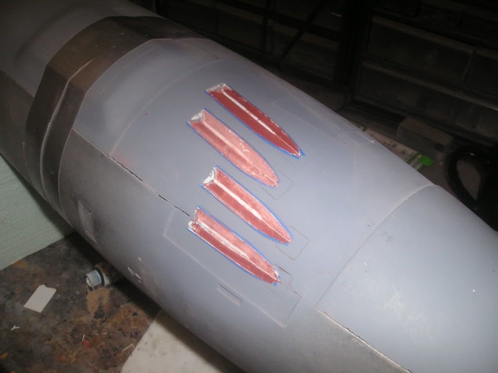
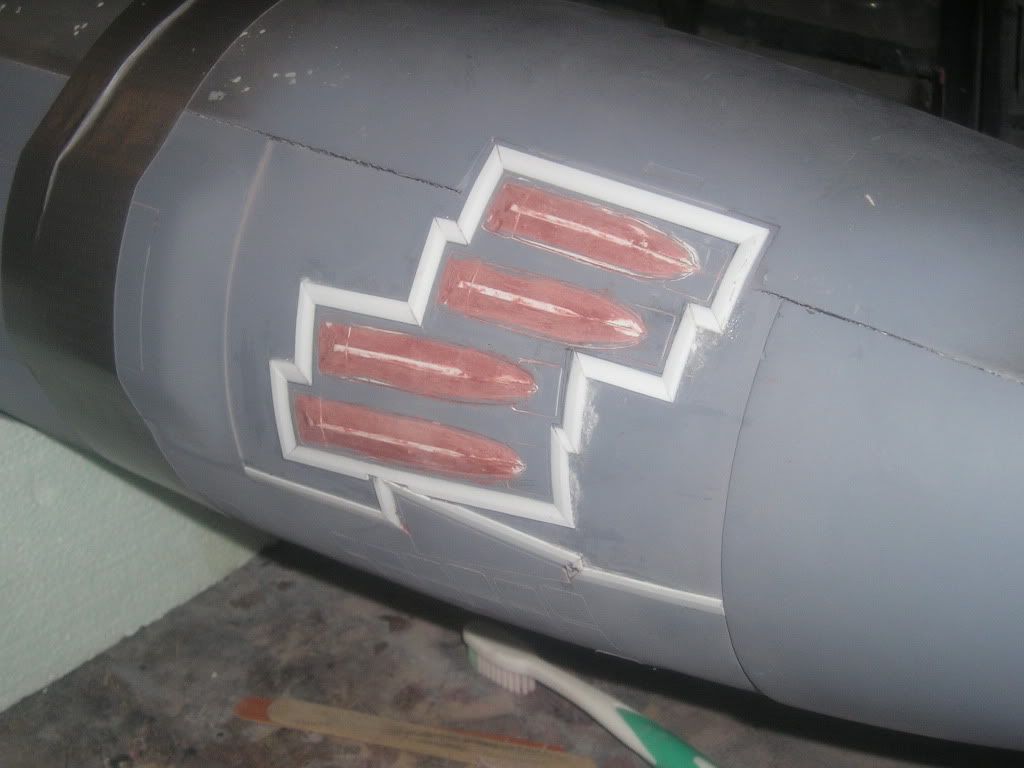
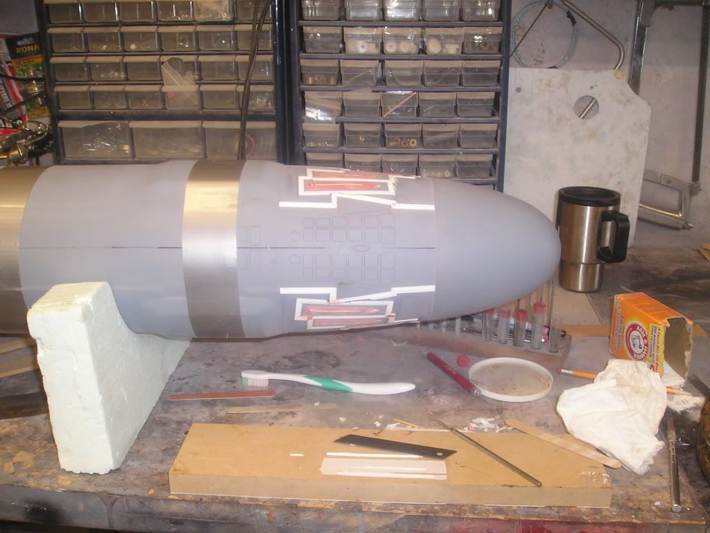
The bevelling around the torpedo shutter is done, so now we have to fill all that empty space in to bring the hull diameter to where it supposed to be at that point. I added a few strips of styrene as guides so i don’t get a big flat spot when I’m sanding
Filler glopped on liberally:
Sanded flush to guide strips]http://i171.photobucket.com/albums/u319/Rapperkiller/Seawolf/P1012883.jpg[/img]
I'm Truly Amazed........... At Your Work!!!!!!1 Geeze You're Good!
You Are A "Master of The Art".......
When I Grow Up...... I Want To Build Just Like You
 Tweet
Tweet


Comment