Thor Alfa, with some twists...

Collapse
X
 
  • Time
  • Show
Clear All
new posts
  • eckloss
    • Nov 2003
    • 1196

    #1

    Thor Alfa, with some twists...

    hello again all...

    i wanted to post my progress from the past two weeks. i had to put the tecumseh aside for a while, so i dug the thor alfa out of storage and decided to take a crack at it.

    no disrespect whatsoever to matt and his gorgeous boats, but we all know that the alfa was incorrect in a few areas, most notably the scribing detail. this is only b/c the information available at the time of the origins of this beautiful boat was far inferior to what we now have, due in no small part to the research of wayne.

    forgive the picture heavy nature of this post...

    but on with the show. please provide feedback, criticisms, suggestions, etc.

    this alfa was bought several years ago, perhaps four. its sat in storage ever since.

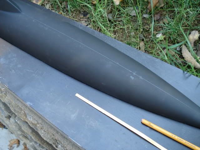
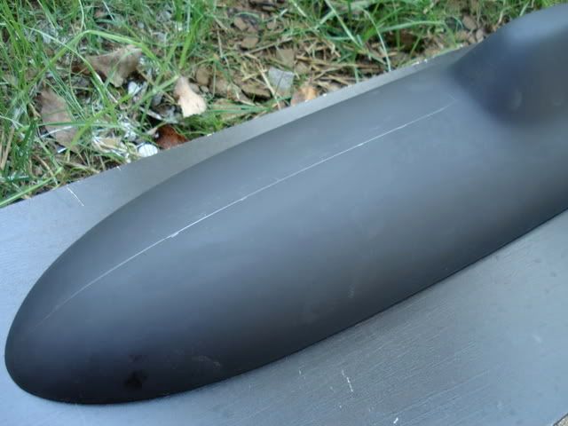
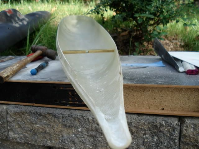
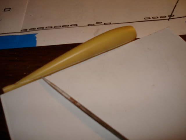
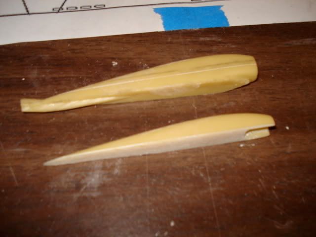
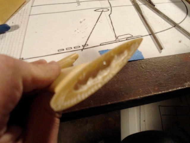
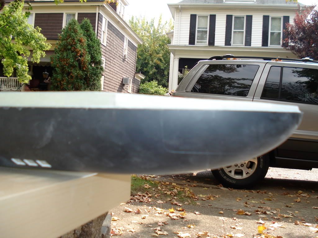
    i wanted to present a more accurate representation of the alfa, at least within my amateur abilities. i did not want to undertake the task of reworking the bow into a more blunt shape as is the case of the real boat, so i left the hull shape itself as-is.

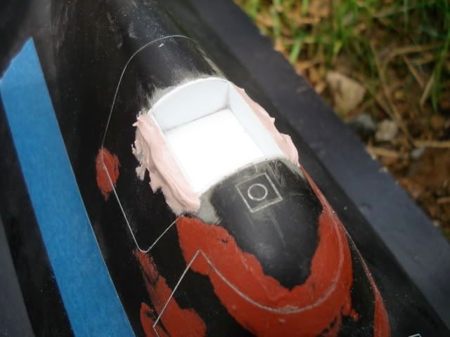
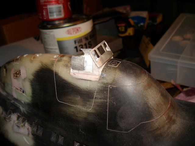
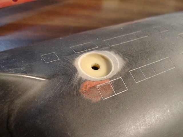
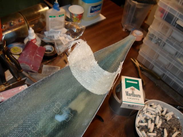
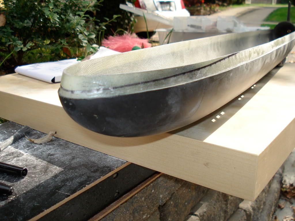
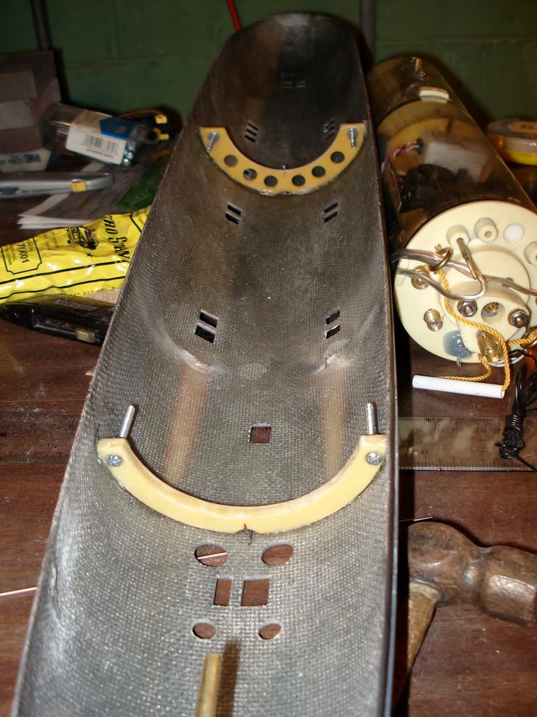
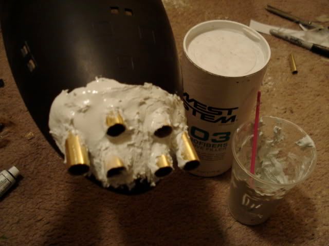
    but when it comes to the scribed detail, i wanted to start fresh with a blank slate. i scraped out all detail on the upper hull half, filled it in with bondo and notrostan, and then gave the whole thing a thin glaze or resin. this way, when scribing in the new details, i wouldnt smack into the old ones. once the new coat cured, i smoothed it down and blasted it with black primer (pencil mark show up very well on flat black)


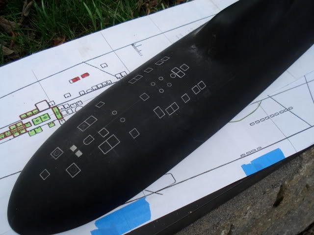
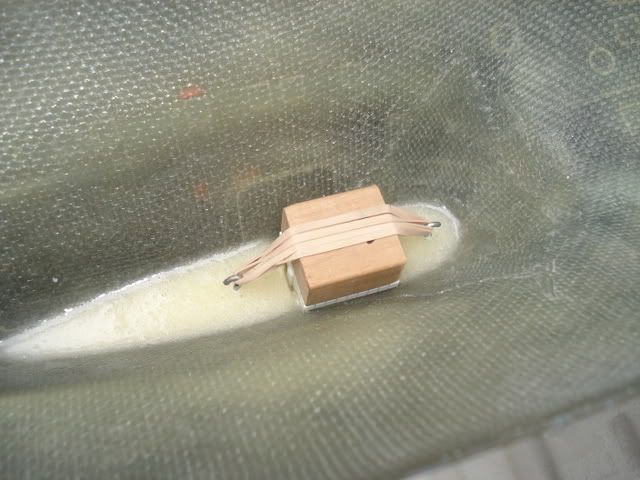
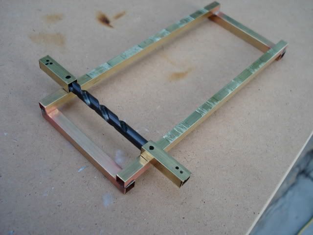
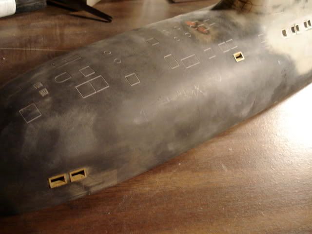
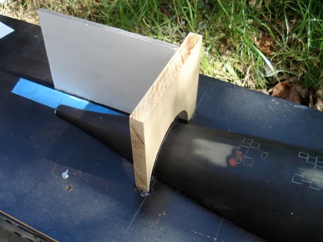
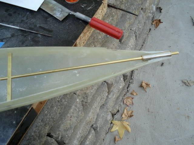
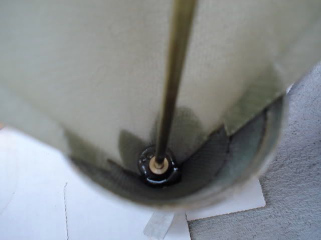
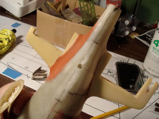
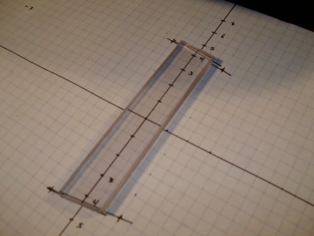
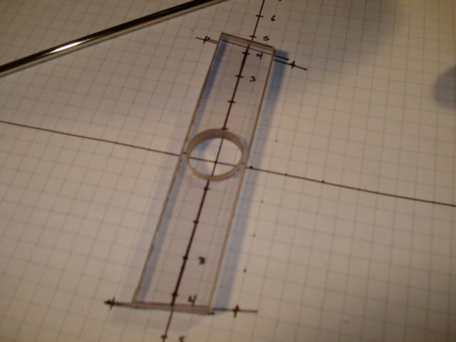
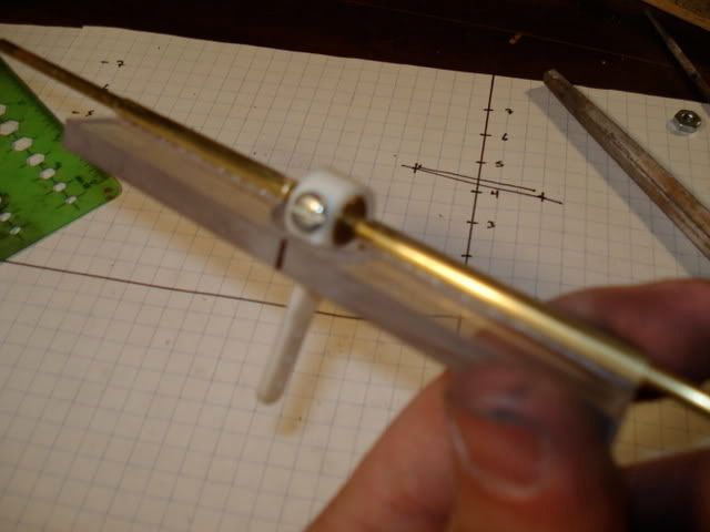
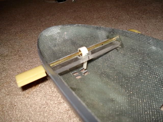
    i marked the hull with a centerline, and then used a crude wooden coutout to give me a but line for the stern half, which in the mean time, i would use as my "zero" point, from which all sequential measurements could be made white transferring details form the plans to the hull.


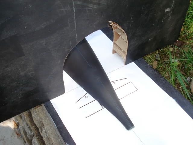
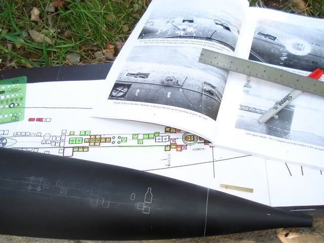
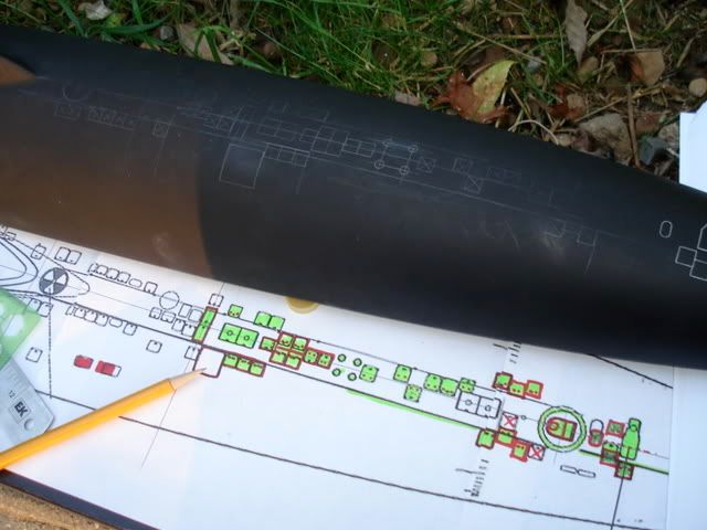
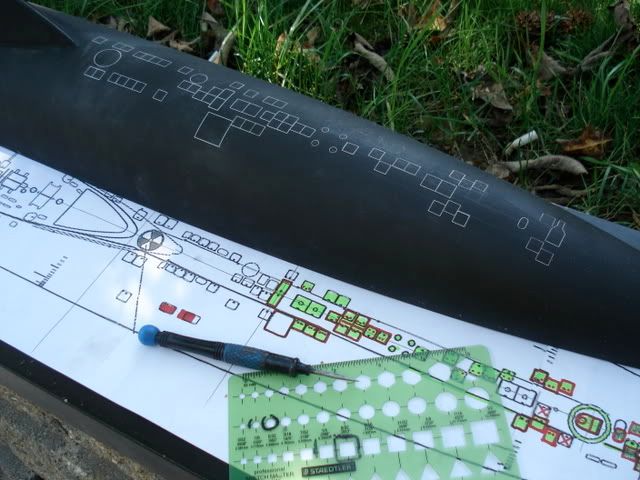
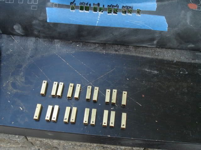
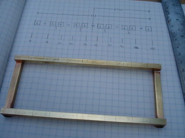
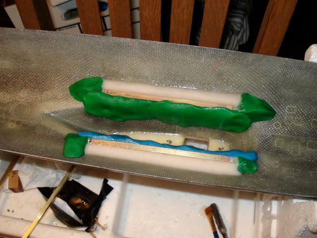
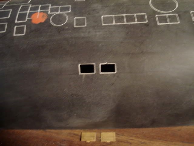
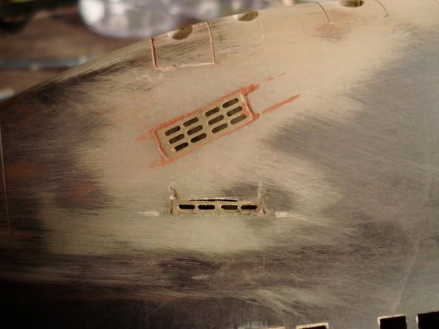
    the plans i am working from came from russian military website. there are several of these available for the alfa, and each has slight differences. i chose the ones i did because they provided the closets, but still not perfect, arrangement of hatches, capstans, doors, etc. in the background of some of the photos you may see these plans. those items marked in green are details that i could confirm their existence and position based on actual photographs. those marked in red ink are details that were misshapen or had to be slightly moved based on comparison to photo evidence.

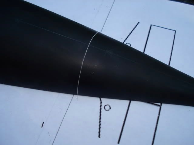
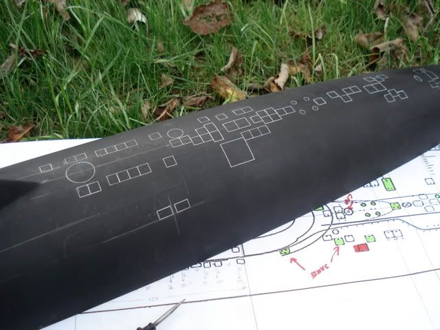
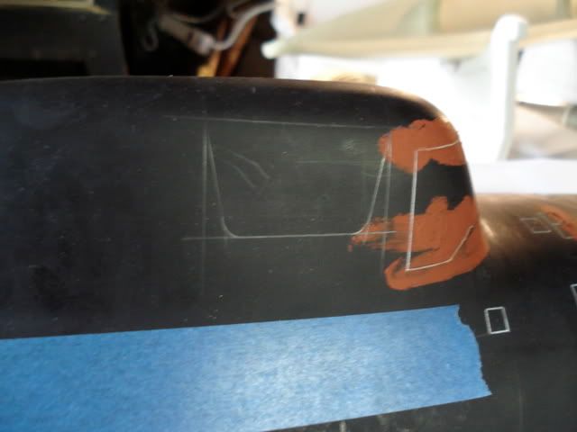
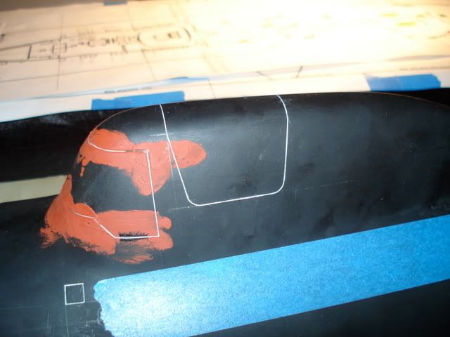
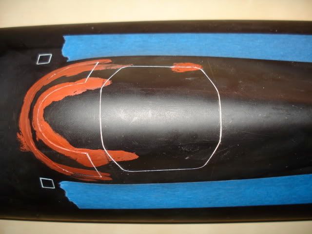
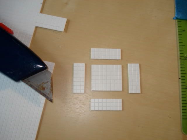
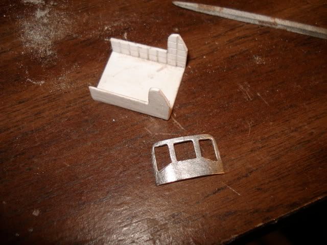
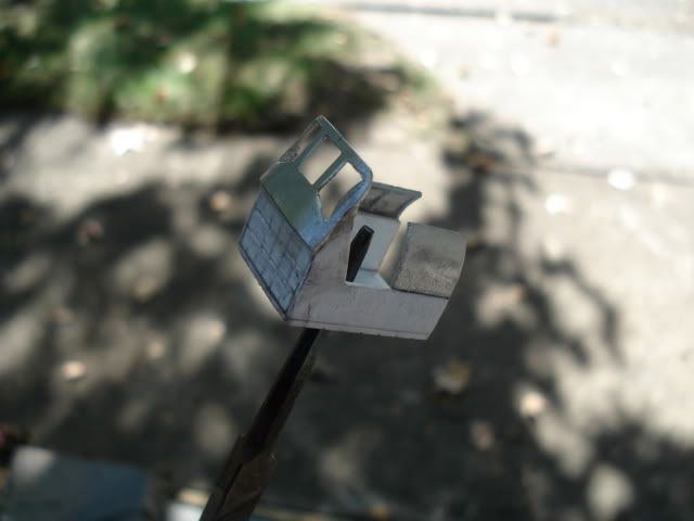
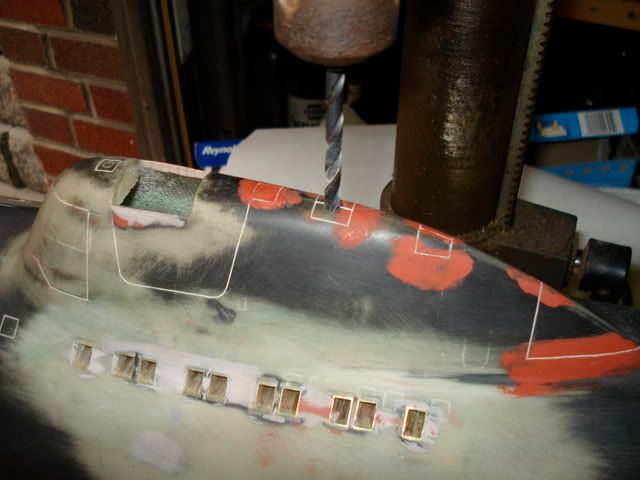
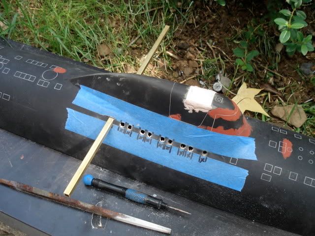
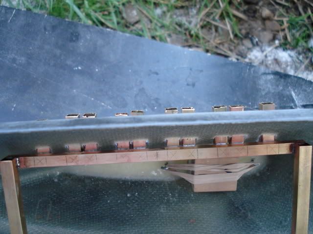
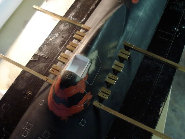
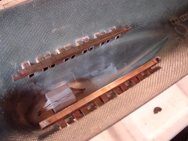
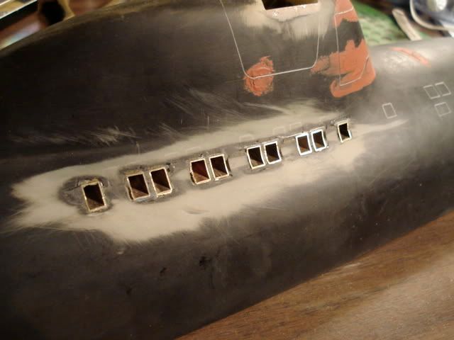
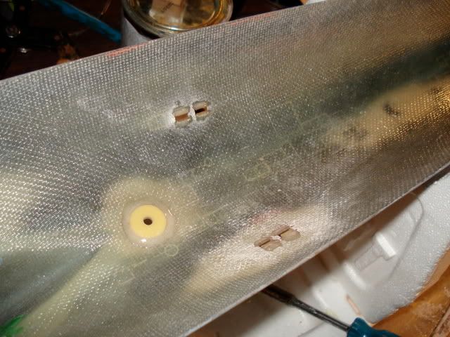
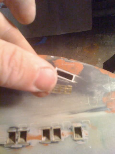
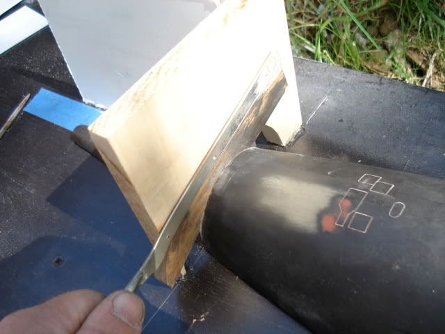
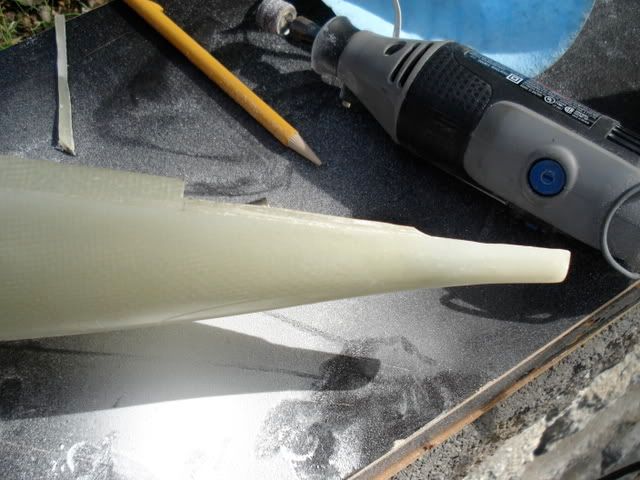
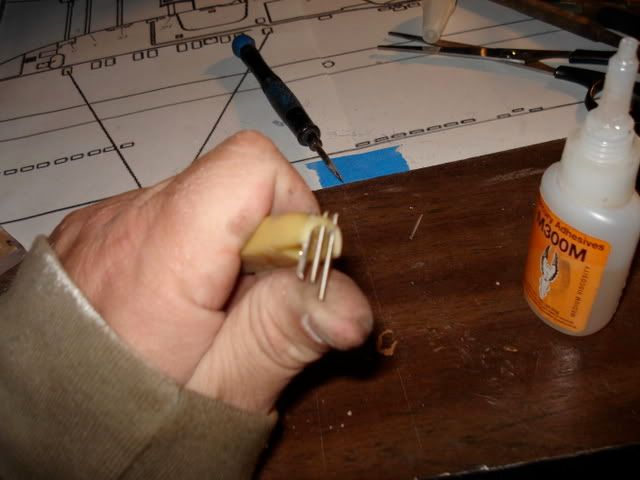
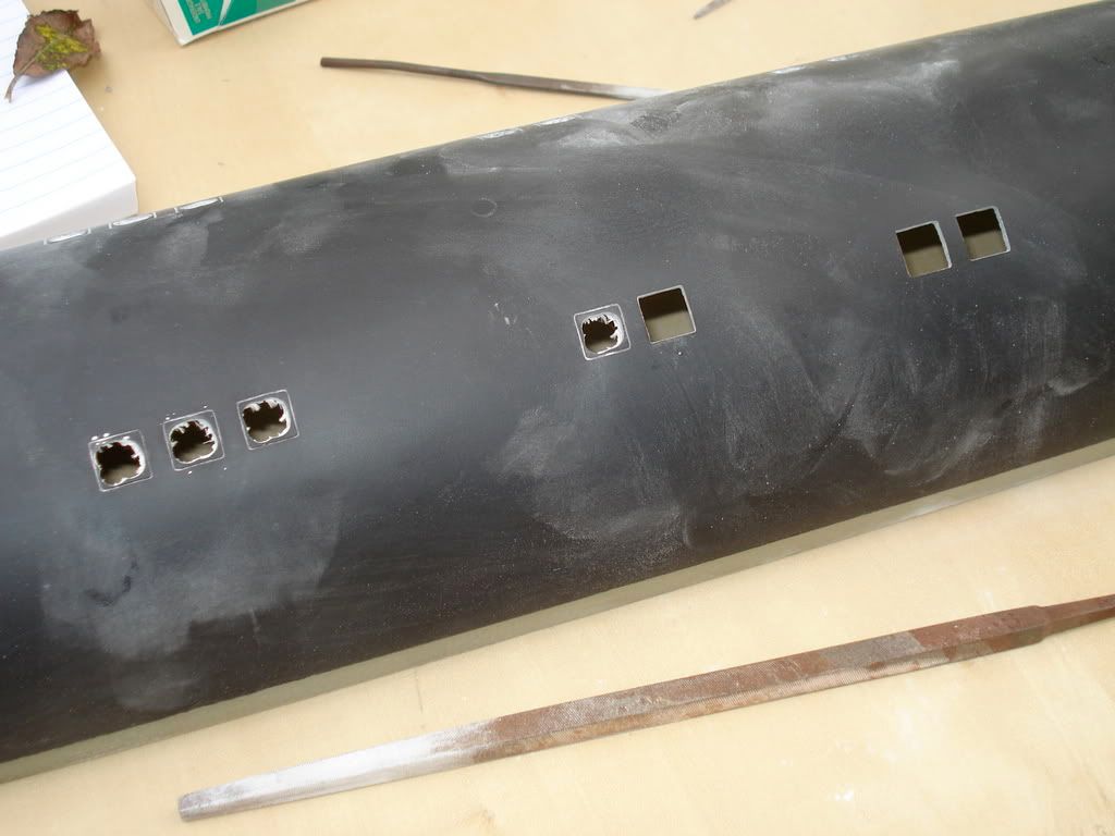
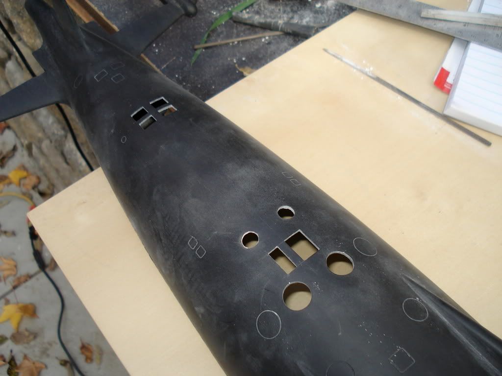
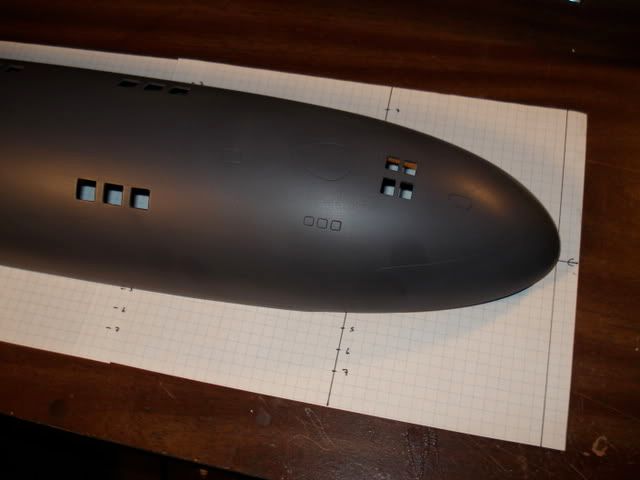
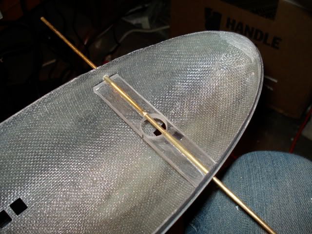
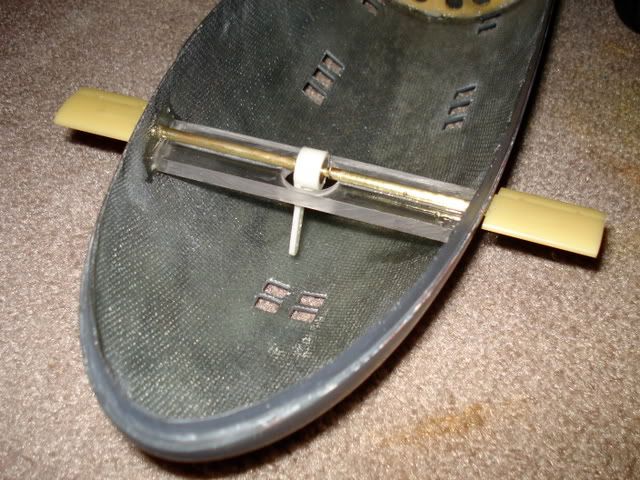
    the task or resribing is pretty straightforward. once i determined the distance and location from the marked starting point on the plans, that detail was penciled in on the hull and then scribed in once i was happy this its position. here a few photos of scribing in progress.....


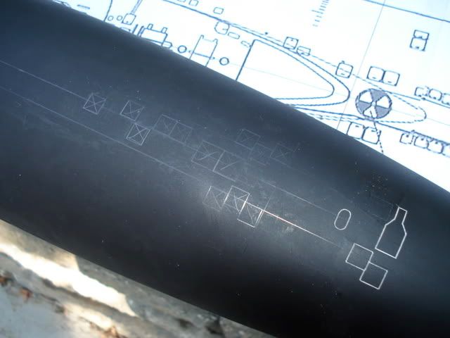
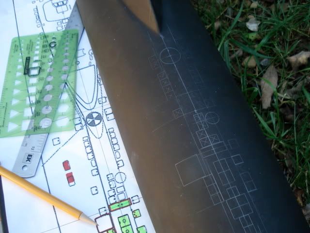
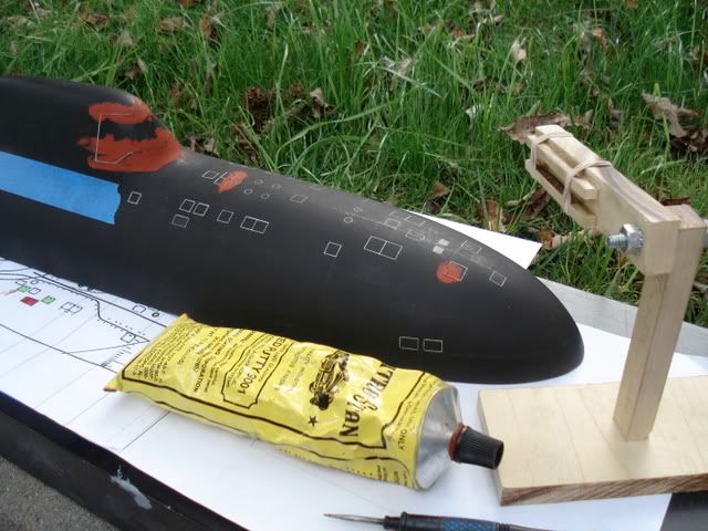
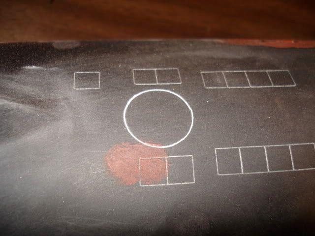
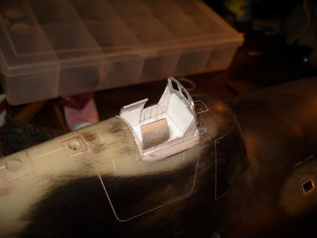
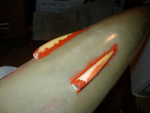
    as you can see, a little touch up putty was needed from time to time to correct my over-zealous hand!
  • eckloss
    • Nov 2003
    • 1196

    #2
    a little detail work on

    a little detail work on the sail....

    first i scribed in the major details, including the escape module.


    next, i wanted to create an open bridge, with the windshield raised and the hinged doors immediately behind it also open.

    i created a bridge box of 0.40" thick styrene


    next cut the opening in the sail to accommodate it.


    a small block of wood was adhered to the bottom of the bridge box and the whole thing set in place. note the excess that needs trimmed away still.


    turning the upper hull upside down, i poured in a generous thickness of resin to surround the bridge box form underneath, and also to act as a mass to cut through to help keep the masts and scopes straight. more on that in a minute...


    the excess stryene sticking out of the sail was trimmed away and bondo was used to fill in the gaps and contour the sail right up to the edge of the bridge box.


    next came the bridge assembly. i created another box that would slide down into the bridge opening. on it, i placed the windshield and the hinged doors, all with a little extra support from some carefully cut styrene sections


    once the fit was confirmed, it was removed and primered. this removable part is held in place by a set screw in the floor of the bridge, so that i can remove this delicate piece and safely stow it for transport.


    Comment

    • eckloss
      • Nov 2003
      • 1196

      #3
      scopes and masts...

      i scavenged these

      scopes and masts...

      i scavenged these from an old akula kit. close enough.

      at the end of each scope rod, i soldered an extension tube and then a small length of treaded rod


      then tapped the sail openings...


      finally, to keep them straight as possible, i soldered buts to a length of square tubing, which lays across underneath of the sail. this rod is in turn held in place by other shorter lengths of square rod with threaded rod soldered in place and protruding out. i tapped holes in the rod with the nuts soldered onto it, so that it will slip over the shorter rods that are permanently affixed to the inner hull, and then place a securing nut to hold it all together. this way, should i ever need to remove the larger rod for repair, i can easily do so.


      the scopes and masts are removable for transport safety. its a simple matter to install them for patrol by lowering them through the opening in the sail and twisting the treaded rod on each onto its corresponding nut on the securing bar below the sail. trust me, they dont move!


      <yes, i know theyre not quite straight. i fixed that. perfectionist communists!!)

      Comment

      • eckloss
        • Nov 2003
        • 1196

        #4
        so in the past few

        so in the past few pics you may have noticed the flood gates under the sail. let me explain this one...

        if you look closely at a good, detail shot of an alfa hull, these are not simple holes in the outer hull, but rather squared tubes with a hinged door (hinged at the bottom). every alfa ive seen built has these holes just cut out of the fiberglass and thats the end of it. i wanted a little more, accurate detail. i needed to represent the 3-dimensional nature of the openings. so here goes my attempt. im thinking it worked out rather well, and gives a great look, even from a slight distance

        first, i cut 20 1" sections of square brass tube.


        then, i fabricated a rectangular tube onto which they would all be soldered. note that the shorter crossbars will later be removed. they are there now for the structural integrity of the jig.


        i marked out the spacing of each section. it should be also noted here that this alfa is modeled as a generic alfa, and not any particular boat in the class. different boats had these flood holes in different groupings and configurations. for example, some have them as a single flood vent, followed by a group of two, another group of two, a third group of 2, then another single, then an final group of two. in other words, 1-2-2-2-1-2. the grouping i used was 1-2-2-2-2-1, which i found most repeated in the photographic references i was using. each section was then soldered to the jig.


        i cut rough openings in the hull below the sail, oversized a bit to allow a little wiggle room. i used larger lengths of square tube to make sure both sides were level and equidistant from the horizontal centerline of the upper hull. the rig was then inserted into the underside of the sail so the tubes stuck out the outsides.


        everything was tack glued into place, and the shorter supporting bars i mentioned above were removed (they would have interfered with the correct placement of the wtc)


        using playdoh (yes, playdoh), i created a cavity surrounding the areas inside the sail around the tubes and poured in resin to permanently set them in place.


        the excess tubing was removed from the outer hull and eventually sanded down to be completely flush and correctly contoured to the hull.


        Comment

        • eckloss
          • Nov 2003
          • 1196

          #5
          brass hull openings were also

          brass hull openings were also scavenged from the akula kit. i used these for the upper hull flood holes on the bow and stern of the upper hull half.


          also note above, i have installed the buoy housing and made it flush with the hull, seen closer here


          everything was further secured by a mixture of resin and microfiber filler, but the buoy and the hull openings.

          Comment

          • eckloss
            • Nov 2003
            • 1196

            #6
            adding a little more detail

            adding a little more detail to the sail...

            i used some photo etched brass to represent some of the tiny openings in the sail. the rough shape was dug out of the glass apx 1/16" deep and the center portion then completely removed, so that these opening do indeed go all the way through the hull. sorry i dont have many pics of the actual sanded and finished product, but you get the idea...


            Comment

            • eckloss
              • Nov 2003
              • 1196

              #7
              stern cone and appendages...

              before cutting

              stern cone and appendages...

              before cutting the upper hull, i laid in several coats of mold release. the stuff is thin and dries quickly. i use it right overtop of the the rough side of the existing glass and it gives me an easy pop-off indexing strip every time.


              i then cut off the stern cone to be attached to the lower hull half. i built a quick rig to keep my cut square and perfect.


              a little trimming needed to be done to remove the excess resin and such from the stern of the lower hull...


              i then bored in a rough gouge for the prop shaft housing.


              using another section of brass square tube, i cut a small section to wedge into the inside of the lower hull, making sure its centerline and the centerline of the hull were, um, well, aligned! directly in the center of this cross bar i drilled a 3/16" hole all the way through to accommodate the prop shaft. this is only a temporary rig to give me a straight, true alignment of the prop shaft between that rod and the shaft housing at the very stern of the boat. once i had it perfectly aligned, i tack glued the housing in place and also tack glued on the upper stern section to the lower hull. propped up the hull so it stood vertical, and poured in just enough resin to almost reach the top of the shaft housing within the hull. that bastard will never move again, so it had to be 100% straight the first time. last thing i want is a wobbly, vibrating propeller!


              i of course did later add some sections of 1" cloth to better bond the upper and lower hull stern sections and the upper hull indexing strip.

              Comment

              • eckloss
                • Nov 2003
                • 1196

                #8
                water intakes...

                the original were a

                water intakes...

                the original were a bit oversized. so i cut them down. i also added three small rods to roughly represent the actual rods present in the real boats.


                Comment

                • eckloss
                  • Nov 2003
                  • 1196

                  #9
                  planes and rudders...

                  pretty straightforward. i

                  planes and rudders...

                  pretty straightforward. i gouged out some extra space within each appendage to hold a putty-like mixture of resin and microfibers. i tack glued the ends to the hull to keep them from moving while the resin mix cured. solid as a rock. in fact, a bit ago, the hull took a tumble off a table and landed on the top rudder. although it broke the rudder in three places, it didnt separate from the hull. ha!


                  thats it for now. i was hoping to have it done for this weekend, but i guess the kid does need attention sometimes, too

                  im off to virginia beach saturday to pick up my vanguard from david. then ill see all you SCEast members at the YMCA on sunday!

                  until next time..

                  erich

                  Comment

                  • eckloss
                    • Nov 2003
                    • 1196

                    #10
                    just a bit more work

                    just a bit more work to report.

                    opened up the flood holes in the bottom hull. pretty straightforward.


                    to get the top and bottom hull halves to sit properly, much of the bow indexing lip had to be shaved down and beveled. to make sure i had symmetry, i cut a mirrored pattern out of contact paper and laid it over the lip. the paper was actually clear, so you can see i colored in the edge with a black sharpie so i could more easily see the line. then simply cut away the excess with a dremel sanding drum, and then beveled the upper edge inwards as well.


                    getting the wtc saddles in place. installed screws in each end for rubber bands to hold the wtc down, and in the forward saddle i installed a 1/16" pin bottom center that installs in a corresponding hole in the bottom of the wtc's ballast area, simply to make sure the wtc sits in the exact same spot each time. they are simply tack glued in place for now....i'll reinforce them with some resin and microfiber filler today. also have been filling holes, scratches, and dents with glazing putty.


                    Comment

                    • eckloss
                      • Nov 2003
                      • 1196

                      #11
                      building the bow planes support....

                      according

                      building the bow planes support....

                      according to the plans im using, the bow planes are to be located 4.5" from the tip of the bow, and apx. 1/2" below centerline.

                      i laid the hull over some grid paper with a longitudinal centerline drawn, and marked off the 4.5" mark on the hull. i also traced the contour of the hull onto the paper so i could determine the correct contour & angle at that area.

                      i cut a 1" wide strip of 1/4" thick lexan sheet, then cut a slight groove along its center with a dremel. drilled a 3/4" hole dead center, and cut the ends to match the angle of the hull's interior. also beveled the underside edges to follow the inward slope of the hull.

                      then laid over the groove two sections of 5/32" brass tube and epoxied them into place.

                      drilled 1/8" holes in each side of the hull for the bow planes rods to exit. using a 1/8" brass rod extened thru the hull and the tubing to align everything correctly, i epoxied the support bar within the hull.

                      as you can see, a rocker arm with a set screw fits in the center hole. a length of 1/8" brass rod is slid through one side of the hull, through the brass tubing, through the rocker arm (that will later be linked back to the wtc servo pushrods), and out the other side of the hull. then each dive plane is simply pressure fit onto the lengths of rod extending through each end of the hull.


                      more on monday.

                      Comment

                      • eckloss
                        • Nov 2003
                        • 1196

                        #12
                        torpedo tubes:

                        not intended to be

                        torpedo tubes:

                        not intended to be functional, just for appearance sake.

                        i started by tracing the shape of the hull on some grid paper, and sketching my plans. once i had everything measured out, i cut six lengths of 15/32" tube. then drew out the pattern i needed to cut out of 1/4" thick lexan sheet, and marked the locations of the holes i needed to drill, and pre-punched them slightly to help direct the drill bit. (i drilled then slightly undersized so the tubes would be a very tight fit within them. the whole point is i didnt want them to move, at all)


                        i drilled the holes, then cut the section out using a rotozip and circle-cutting guide. i also cut a bit off of each side edge so as not to interfere with the indexing lip on the lower hull when mated. tapped the tubing sections into place, and pow.... tubes ready!


                        i bored out the bow. yeah, i a little too much maybe. but no big deal. i think i spent more time making sure that everything was aligned properly and straight than i did building this part!


                        i tack glued it in place, enough to hold while i did the next couple steps. i stuffed playdoh (im beginning to love this stuff) in from behind, leaving a small cavity around each tube exit. then filled in the front with evercoat putty.


                        after that set, i removed the playdoh and coated the inner hull with a mixture of resin and chopped fiber.


                        after all that was set, it was a simple task of grinding down the excess material.


                        Comment

                        • petn7
                          Junior Member
                          • Jun 2003
                          • 616

                          #13
                          Wow, you do great work.

                          Wow, you do great work. Ever built a scratch hull?

                          Comment

                          • eckloss
                            • Nov 2003
                            • 1196

                            #14
                            nope. id like to some

                            nope. id like to some day, though.

                            Comment

                            • tmsmalley
                              SubCommittee Member
                              • Feb 2003
                              • 2376

                              #15
                              Neat looking work, Erich. I

                              Neat looking work, Erich. I am wondering if all those open holes will adversly effect the performance of the boat? Are you going to put some covers on them?

                              Comment

                              Working...