Engel Tmax Help Rueqested

Collapse
X
 
  • Time
  • Show
Clear All
new posts
  • JWLaRue
    Managing Editor, SubCommittee Report
    • Aug 1994
    • 4281

    #1

    Engel Tmax Help Rueqested

    Folks,

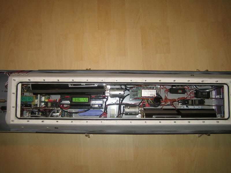
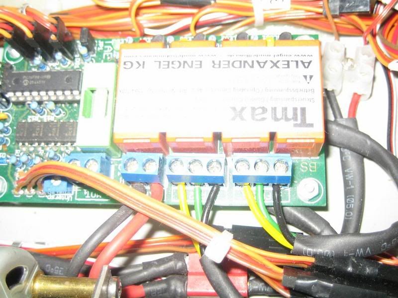
    I have been helping a fellow r/c sub modeler in trying to get the electronics in his Engel Gato working. As of last week, we were able to get just about everything except the ballast system working. The kit uses the new Engel Tmax electronics to control both piston tanks.....and we've had no luck getting it to operate.

    Does anyone have any experience with this system who could lend me a hand? It would be very much appreciated if you could contact me!

    -tnx,

    Jeff
    Rohr 1.....Los!
  • Wheelerdealer
    Junior Member
    • Jun 2006
    • 315

    #2
    I have Tmax working fine,

    I have Tmax working fine, what do you need?


    Ramesh

    Comment

    • bigdave
      Junior Member
      • Feb 2003
      • 3596

      #3
      Jeff,
      You may want to

      Jeff,
      You may want to try and contact Gregor Engel for help. They are always willing to answer any questions. BD.
      sigpic"Eat your pudding Mr Land"
      "I ain't sure it's pudden" 20K

      Comment

      • JWLaRue
        Managing Editor, SubCommittee Report
        • Aug 1994
        • 4281

        #4
        Hi Ramesh,

        Many thanks!

        First let me

        Hi Ramesh,

        Many thanks!

        First let me describe the behavior that we are seeing. This is for the 3-channel configuration. When the system is powered up, both pistons will move from the full empty position to roughly the half full position and then move back to empty. Once that completes, nothing that we do with the transmitter causes any movement of the pistons. The status LEDs show LED1, LED4 and LED5 on solid.

        The first thing I'd like to verify is whether or not the Engel provided wiring diagram is correct. If that can be confirmed, the next questions would be:

        1) to ask about the orientation of the red/brown wires connected to the linear pot that is connected to piston 'full' probe. My diagram notes an outer and inner side, but the additional text for the inner side is missing.

        2) to confirm that the "X" label near one side of each motor on the diagram is intended to represent the positive lead.

        3) for the K5, K6, and K7 connectors on the Tmax, what is the orientation of the receiver wires being connected to them. (e.g. brown/black to the top)

        Any help that you can provide will be greatly appreciated!

        -Jeff

        BigDave: Agreed, Gregor will be my/our next step.
        Rohr 1.....Los!

        Comment

        • Wheelerdealer
          Junior Member
          • Jun 2006
          • 315

          #5
          Hi Jeff, I have hunted

          Hi Jeff, I have hunted high and low for the my copy for the wiring diagram but I cant track it down for the moment. Regardless, I can conform that I wired it exactly as described. I have take some some pics of the wiring in the bow tank and the linear potentiometer.

          LEDs 1 & 3 should come on when surfacing and 2 & 4 when diving. Te green LED is status indicator led.
          All leds are out when the dive switch is in the middle postion (85% full) and the piston tanks have attained the commanded position. (see video- video sequence is starts of in surfaces postion, 85% full, 100% full, back to 85% full and finally back to surfaced position)

          The wire next black + on the motor goes to the microswitch furtes away (partially hidden in the picture). I rememer reversing the wires to the motor so it would work in the required manner.


          K5,6 and 7 are wired brown to negative on reciever, red to positve and orange to signal on the reciever. I am using a Graupner Rx which comes with the same coloured wires and a polarized plug that goes into the RX so it only fits oneway. Regardless Brown - negative, Red - positive, orange signal.

          The TMAX unit needs 3 proportional channels for full functionality (using an expansion module with switches and rotatory proportional knobs did not work for me). However it works like a TAE controller off just one channel (the 3 postion dive switch) if you disconnect the wires from the linear pot and the corresponding K connectors. You may want to test it this way to simplify thing. My boat runs on 6 volts and I had to adjust the low voltage cut off accordingly. Also disconnect the pressure sensor (2 wires) when testing, in case it is faulty and triping.

          Check the bottom of the unit to make sure no solder tracks are broken/burnt - I managed to burn one out when wiring it the fist time and to bridge the break.


          Click for video

          Comment

          • Wheelerdealer
            Junior Member
            • Jun 2006
            • 315

            #6
            Oh, and you need to

            Oh, and you need to have main battery power to the TMax board before you switch on power to the Rx.

            Comment

            • JWLaRue
              Managing Editor, SubCommittee Report
              • Aug 1994
              • 4281

              #7
              Hi Ramesh,

              Great information! This is

              Hi Ramesh,

              Great information! This is very much appreciated.

              I'll report back once we've had a chance to try it.

              -Jeff
              Rohr 1.....Los!

              Comment

              Working...