1/25 Type VIIC/41 Scratch Build.

Collapse
X
 
  • Time
  • Show
Clear All
new posts
  • paul von braun
    Junior Member
    • Jun 2004
    • 242

    #61
    Have just returned from the

    Have just returned from the fatherland this very minute!!! We went to the Bavaria film studios and had a great time - the Das Boot set was only a small part of the 90 minute tour. However, I have lots of photographs courtesy of Nikki and our friend Mark, plus video footage that I shot.
    I will put the photographs on here soon, but the video.... rapidshare?


    Paul.
    Comment

    • Guest

      #62
      rapidshare?


      Paul.

      How about putfile.com or youtube?

      rapidshare?


      Paul.
      How about putfile.com or youtube?

      Comment

      • paul von braun
        Junior Member
        • Jun 2004
        • 242

        #63
        Well, with rapidshare I can

        Well, with rapidshare I can put the video on the net with no loss of quality and it will be downloadable for free, rather than just the ability to watch it in a nasty pixely manner. Only problem is that sometimes it can be difficult to use - well see.

        Paul.

        Comment

        • mylo
          Junior Member
          • Aug 2005
          • 723

          #64
          ** UPDATE **

          Work is

          ** UPDATE **

          Work is progressing on the type VIIc/41.

          The hull and tower are ready for glassing. I have been looking all over for West Systems Epoxy with no luck. I may have to use polyester resin. In the meantime, work is being completed on the many handrails of the wintergartens and main deck. I've had many "first" experiences so far in this build and soldering 3/32" brass rod is another. Stay tuned on how I make out with that.

          I fully expect my next sub to take half the time to build due to the learning curve of trying to figure out all these new skills.

          New computer is on order.

          That is all,

          Mylo

          Comment

          • Guest

            #65
            OTW Type VII is cast

            OTW Type VII is cast in polyester resin. I've not heard any complaints to date of that kit.

            Comment

            • paul von braun
              Junior Member
              • Jun 2004
              • 242

              #66
              Mylo,
              try this...

              http://www.westsystem.com/

              Paul.

              Mylo,
              try this...

              The home of WEST SYSTEM marine-grade epoxy resins and hardeners for boat building, boat repair, home repair, and restoration.


              Paul.

              Comment

              • koeze
                Junior Member
                • May 2003
                • 204

                #67
                I have all my photo's

                I have all my photo's from my visit to U995 on a photoserver.

                http://album.zoom.nl/user/KOEZE/U-995/login/
                Log in using wachtwoord (password) "subcommittee" and you'll be able to download the full res (4MP) images.

                Good work by the way. Nice documentation.

                Oh, and just a few comments on some of the info in the thread.
                U995 was originally built as a VIIc/41 with a dual Wintergarten tower.
                The photo's of the "wrecked" U995 is in fact U-Kaura. U995 was used by the Norvegian Navy after WWII. In I believe 1969 they stopped using her and she ended up rotting away.
                In the years she has been on display in Laboe (near Kiel) there have been a large number of hefty repairs to the hull. Check the images on the bow. You'll see that nearly all of the bow have been replaced by welded hull plating. Torpedo tube doors have been welded over.

                Erik Jan

                Comment

                • mylo
                  Junior Member
                  • Aug 2005
                  • 723

                  #68
                  My apologies for the delay

                  My apologies for the delay in updating this thread. I've had a number of technical problems to work out. Good new is, I seem to be back up and running.

                  ....enjoy the continuation of this build.


                  [b]Step 38 ]

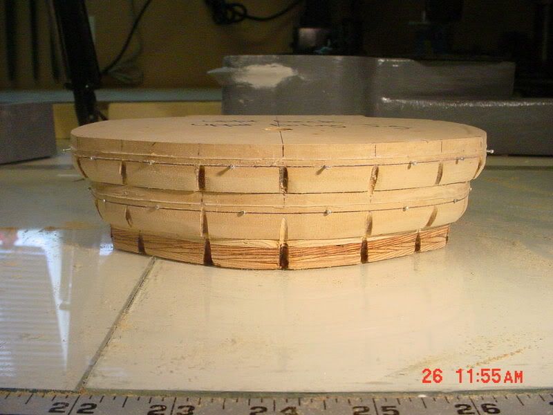
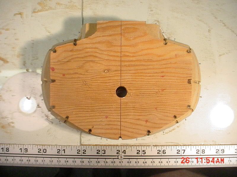
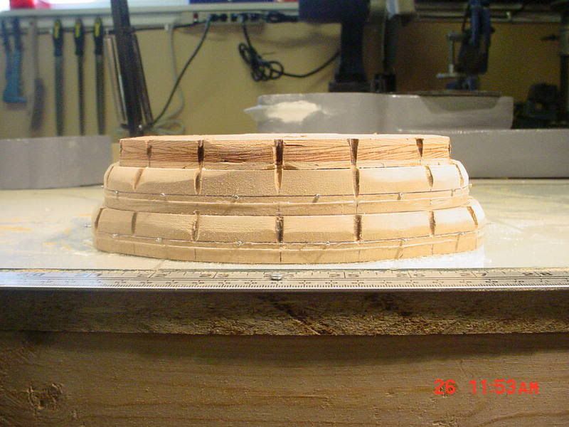
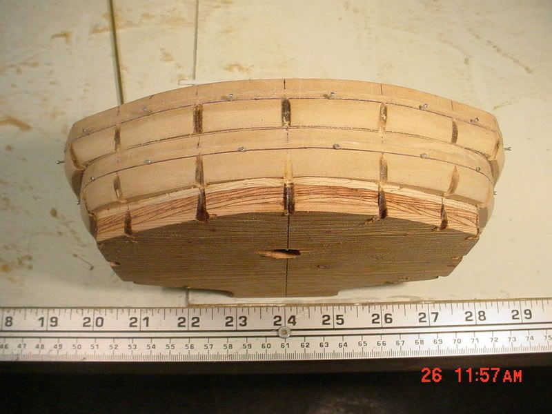
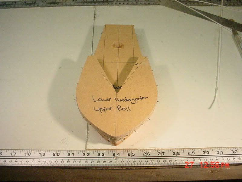
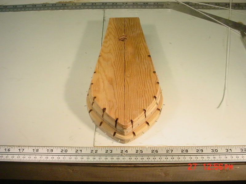
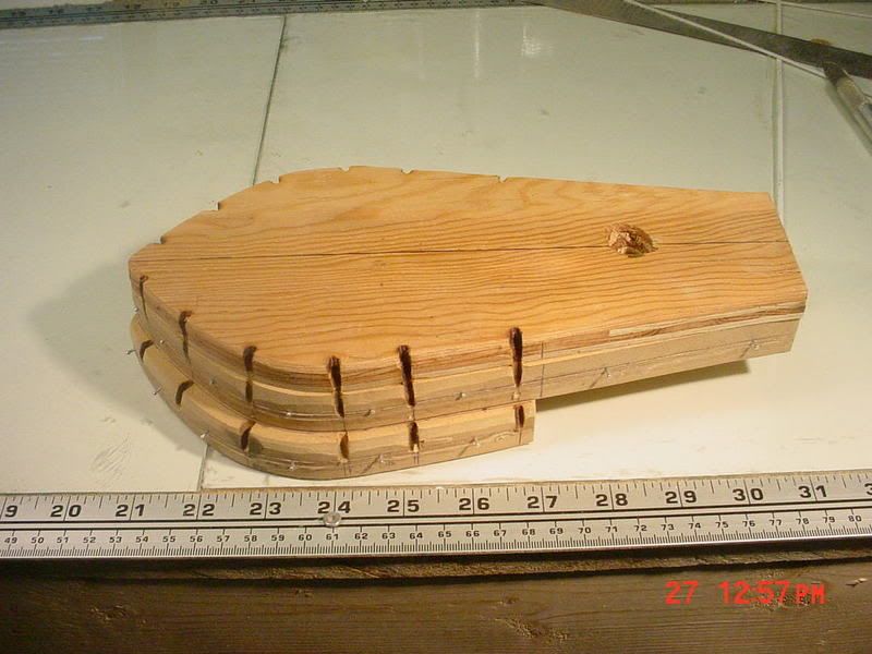
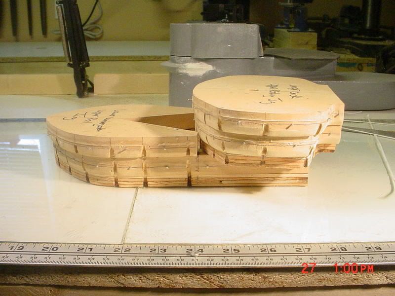
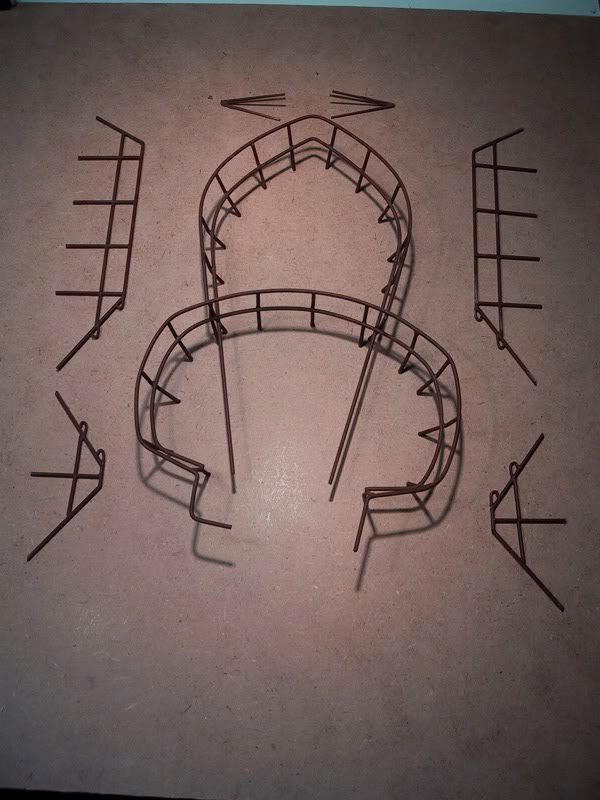
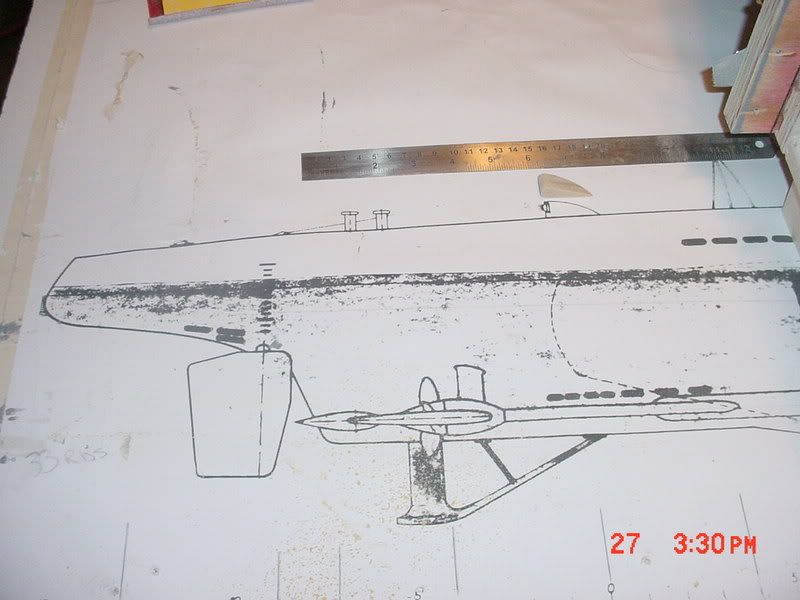
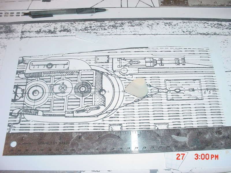
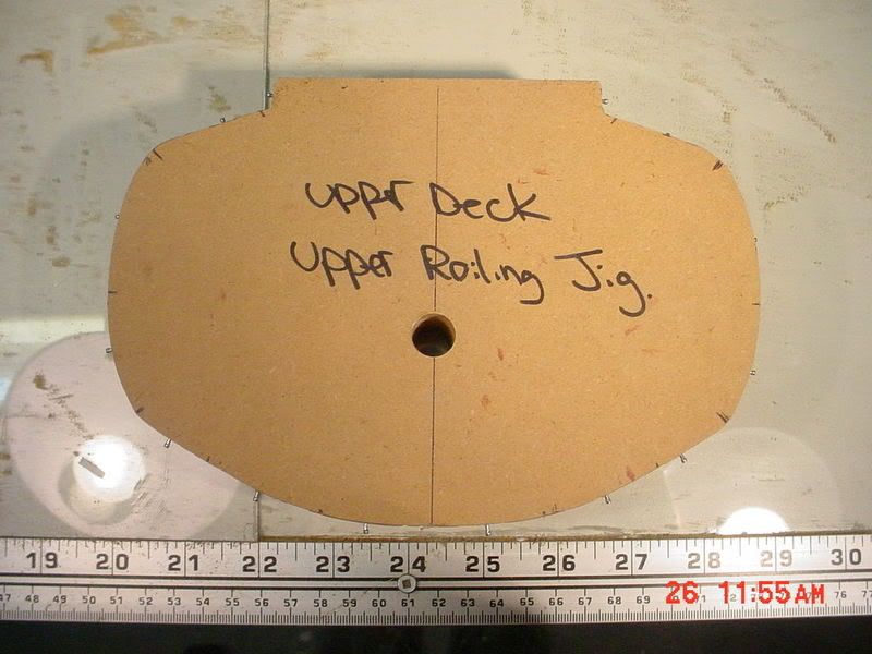
                  The handrailings would require jigs in order to build them with any degree of accuracy. The highly complex shapes of the upper and lower railings of both the upper and lower wintergartens simply made the construction of the jigs a requirement. The whole process of building the jigs could just be considered part of the rail building phase.

                  The jigs were built using 3/4" MDF. Using a copies of the photocopied tower plans, four separate railing profiles were cut out as well as the bottom deck profiles. The six pieces include :

                  1) The upper railing of the upper wintergarten
                  2) The lower railing of the upper wintergarten
                  3) The upper railing of the lower wintergarten
                  4) The lower railing of the lower wintergarten
                  5) The upper deck
                  6) The lower deck

                  These templates were then traced onto a piece of MDF and cut out. A line was marked in the exact centre of the width for the pieces that represented the railings. This line is where the actual 3/32" brass rod would be placed. This was calculated taking measurements off the plans which showed that the railings were 3/4" apart. Given that, if the brass rods were placed in the centre of each piece of 3/4" MDF, there would be 3/4" distance between the two. I have included many photos with this phase to help clarify.


                  Once the six pieces were cut, their respective upper/lower wintergarten pieces were laminated together using gorilla glue. Care had to be taken to ensure the three pieces of each wintergarten jig were in alignment.

                  Once the glue had cured, a bevel shape was put on to help getting the railing assembly off the jig once built. After beveling, tiny finishing nails were put in to act as a rest for the 3/32" brass rod. The nails were placed in such a way so that the brass rod would be right on the centre line. Notches were then shaped using a rotary tool to allow for the placement of the vertical rails.

                  The side railing jigs were built by taking the measurements from the plans and drawing onto a piece of MDF. Narrow strips of hardboard were cut and glued beside the drawn lines with just enough space to allow a piece of 3/32" rod to fit.

                  The rear antanae mount jigs were built using MDF with dimensions taken from the plans.

                  The construction of the jigs took 8 hours.

                  Using the jigs, the 3/32" brass rod was moulded and shaped, and bent, and manipulated, ...and moulded some more, until it conformed to the jig. Once the four railings were put on the jig in this manner, the vertical rails were set in place. Now it was time to solder.

                  What I discovered is that a "normal" soldering gun doesn't make enough heat to solder 3/32" brass rod. My first attempt resulted in not enough heat, which meant a cold solder joint, which meant very brittle, which meant the railing assembly completely broke apart when I tried to remove it from the jig. .....time to use the torch.

                  I was unsure whether my MDF jigs would hold up to the heat generated by the torch, but, ....I had to go for it. The torch worked great on the LOWEST possible flame setting. I tried not to damage the jigs any more that I had to. They blackened, but the material remained intact. I can not say the same for the side railing jig. The narrow strips of hardboard were damaged quite a bit, but I WAS able to get the two railings built.


                  Once soldered, all the joints were ground with the rotary tool and then hit with the stainless wire brush, again on the rotary tool. ...basically like miniature welding.

                  The railing assemblies were then sprayed with primer. Once the primer was dry, the railings were test fitted onto the tower. Perfect fit. Again, showing the value of well constructed jigs. I can not stress enough the importance of taking the time to build jigs when they are required. These railings would not have been done without them.


                  More to come

                  Comment

                  • mylo
                    Junior Member
                    • Aug 2005
                    • 723

                    #69
                    Step 39 ]

                    These small pieces

                    [b]Step 39 ]

                    These small pieces were built like all the others up to this point. Template taken from plans, traced onto MDF, cut, sanded, and shaped. I had lost a few of the photos I had taken of this phase when my computer "sunk" a while ago.


                    At this point, I heat treated a piece of wire used for hanging pictures. This stuff is like really small "cable", perfect for use in the upper railings. Since when I bought this wire is was coiled and "springy". I attached one end in my vice and the other in my drill press which was 3' away. Using the movable table on the drill press, I stretched the wire taught. I then heated the wire to a red glow with my torch. I left the wire overnight. Once removed from my "wire straightening jig", the wire was perfectly straightened and would work well for the railing application.


                    More to come

                    Mylo

                    Comment

                    • mylo
                      Junior Member
                      • Aug 2005
                      • 723

                      #70
                      Step 40 ]

                      I decided

                      [b]Step 40 ]

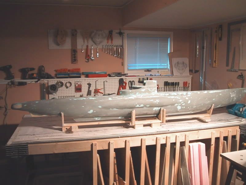
                      I decided to go ahead and glass the hull / tower with polyester resin since my test piece earlier was showing that this could be done without damaging the foam as long as it was painted with oil based paint prior. I did not use fibreglass cloth in this phase for a couple reasons:

                      1) I was building a mould plug and not a "one off" hull, therefore I did not need the strenth of the cloth added to the resin.

                      2) Adding the cloth at this point would take away some of the finer detail of the hull / tower.

                      The resin was applied using a paint brush in small batches since the working time of this stuff was about 10 minutes....and once it sets up, you're done. I tried to smooth it on the best I could knowing that it would speed the sanding process. I gave the hull and tower two coates with a scuffing using coarse sand paper in between coates to knock off the rough edges.

                      Once the second coat was cured, out came the sandpaper. 40, 80, 100, 220 grit paper was used in succession.

                      This phase is not rocket science, just a lot of elbow work....literally.

                      I had lost all the photos I had taken of this phase but again, I don't feel the photos are really important to clarify what has to happen. Sand it 'till it's smooth, pretty simple.

                      Be prepared to have your house smell like a chemical factory for about a week if you use this polyester resin.


                      More to come,

                      Mylo

                      Comment

                      • mylo
                        Junior Member
                        • Aug 2005
                        • 723

                        #71
                        Step 41 ]


                        I decided to

                        [b]Step 41 ]


                        I decided to paint the MDF pieces prior to glassing to keep the process uniform and as well, the paint filled in some tiny flaws and imperfections on the MDF. Once the paint was dry and sanded, they were all glassed with only one coat. After the resin had cured, they were sanded to a smooth finish with 100 followed by 220 grit. These pieces didn't need as much sanding work as the hull / tower likely due to the smoother painted surface. They were all small though and care had to be taken to get into all the tiny areas.


                        More to come,


                        Mylo

                        Comment

                        • mylo
                          Junior Member
                          • Aug 2005
                          • 723

                          #72
                          Step 42 ]


                          This is

                          [b]Step 42 ]


                          This is the last time I'm going to say this.....doing the final spot putty filling / sanding took longer than I anticipated. There, I'm done saying that.

                          This is the phase where every imperfection I could find in the now glassed/sanded hull and tower was filled with polyester spot putty and sanded. I was AMAZED how much imperfection there actually was when I started looking close. What I thought was a pretty decent job on the glassing and sanding, turned out to be only "marginal".

                          The working time of this spot putty once the hardener is added is about 2 minutes.....so I discovered. I was thinking I was going to have about 10 like the resin, ....but I was wrong and so much of my first batch was wasted. Any longer than this and the stuff starts to get "crumbly" from it's original smooth texture. Needless to say, a lot of time was spent mixing up the putty in small little blobs. So off I went filling all the little flaws I could find. The nice thing about this putty is it's sandable in a couple hours.

                          Once I sanded my FIRST pass at the hull, I discovered flaws that I never noticed before....maybe it was because since the hull was getting better, the tiny things I overlooked before were now....noticable. In any case, out came the putty again and I started filling. It took five passes (spot putty, then sand) with the spot putty to get the hull where I was satisfied with it. The tower was much the same. I then finished off by giving everything a good going over with 220 grit. It was smooth and ready for primer.


                          More to come,


                          Mylo

                          Comment

                          • stark
                            Junior Member
                            • Jul 2006
                            • 243

                            #73
                            Mylo I must say you

                            Mylo I must say you are doing a fantastic job Sir, your skill level and presentation are very impressive to me! Sorry for not mentioning this sooner!

                            That is one big sucker and I look so forward to seeing you getting her wet!

                            It would be nice to see what else you have built.

                            I remember a post before, where you asked where to get these plans; your question led me to the same prints, so thanks.

                            Brian Stark

                            Comment

                            • anonymous

                              #74
                              Outstanding! What more can I

                              Outstanding! What more can I say.

                              steve

                              Comment

                              • tmsmalley
                                SubCommittee Member
                                • Feb 2003
                                • 2376

                                #75
                                Great work, Ronald. I appreciate

                                Great work, Ronald. I appreciate you sharing your build with us! What a great sub this is going to be.

                                Comment

                                Working...