1:72 Thor Alfa

Collapse
X
 
  • Time
  • Show
Clear All
new posts
  • eckloss
    • Nov 2003
    • 1196

    #1

    1:72 Thor Alfa

    Yesterday I was hunting for a long lost tool and I bumped into a long box. Low and behold it held a 1994 release of the first iteration of Matt Thor's Alfa kit (first version, without the creeper motors). It followed me upstairs, and this morning I took it out for a good look see. 12 hours later I find myself having got lost in tinkering with it all day. I needed a good distraction, I guess. So as I build the Russian Delfin on one side of the room, looks like I'll be taking some time out for the Alfa as well.

    The pictures tell the story.

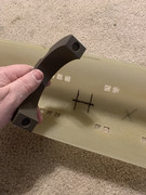
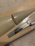
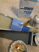
    I cut out the hull openings. Printed the lower set of two pair of saddles. Upper and lower both. Lower to act as WTC saddles, upper to provide a tiny bit of correction to the form of the upper hull, which has bowed outwards ever so slightly over the yeas. But only slightly. A testament to the quality of Matt's fiberglassing skills.

    Cut the stern of the upper hull and glassed it to the bottom half.

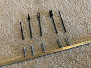
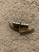
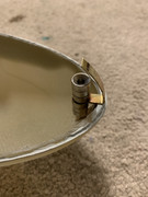
    You will see indentations on the edges of the saddles. The intention is to mount 10mm magnets, sticking out on the lower saddles and indented on the upper ones, to act as both hull half alignment and as a method to join the upper and lower halves. There will also be further pairs of magnets in the bow and at the stern.

    -erich

    (sorry, the pictures are out of order and some need rotated)


  • sam reichart
    Past President
    • Feb 2003
    • 1325

    #2
    One of my favorites boats, and one of the best running models I ever owned. I had the early version as well, and I ran it with a D&E WTC 3.5 and a big gel cell battery. That model was simple to build, and a joy to drive. Good luck with running yours.

    Comment

    • salmon
      Treasurer
      • Jul 2011
      • 2342

      #3
      Great photos! They tell a story indeed!
      If you can cut, drill, saw, hit things and swear a lot, you're well on the way to building a working model sub.

      Comment

      • eckloss
        • Nov 2003
        • 1196

        #4
        Here's a short video showing the placement and use of the magnetically joined hull saddles


        Comment

        • salmon
          Treasurer
          • Jul 2011
          • 2342

          #5
          Erich,
          I will have to steal this idea for a Thor LA I have waiting to be built or a Blueback.....hmmm so many possibilities. I love the use of magnets and what I like about your design is that there is a socket the magnet goes into. It helps prevent the sheer movement on a magnet (pulling a magnet apart is hard, but sliding it sideways it will separate).
          Well done sir!
          Peace,
          Tom
          If you can cut, drill, saw, hit things and swear a lot, you're well on the way to building a working model sub.

          Comment

          • eckloss
            • Nov 2003
            • 1196

            #6
            Thanks, Tom. Magnets are such versatile little buggers for small builds like this. I've done this before using sheets of G11 and drilling holes for the magnets to rest in. But with the advent of 3D printers this becomes so much easier. I put in a little wiggle room into the holes in which the magnets rest. They are 10mm in diameter, and I printed the holes at 10.5mm, just in case there is any slop in the alignment. Seems to be working out great so far.

            Comment

            • Parallax
              SubCommittee Member
              • Aug 2017
              • 195

              #7
              Erich that is brilliant. I'm with Tom, 100 percent stealing how you did this for the Akula saddles.

              Comment

              • eckloss
                • Nov 2003
                • 1196

                #8
                Make sure you leave some pass-throughs so that the water can flow freely through the bottom saddles, and so the air can flow freely through the upper ones

                Click image for larger version

Name:	Screen Shot 2019-04-22 at 1.34.53 AM.jpg
Views:	1
Size:	4.4 KB
ID:	133255

                Comment

                • salmon
                  Treasurer
                  • Jul 2011
                  • 2342

                  #9
                  Thank you, will do!
                  If you can cut, drill, saw, hit things and swear a lot, you're well on the way to building a working model sub.

                  Comment

                  • eckloss
                    • Nov 2003
                    • 1196

                    #10
                    Added the scopes this afternoon. Sorry, the pictures are out of order. Basically what I did is take a 1/4" square brass rod and drill holes in it that measured the same distances as scope cut holes I made on the sail. I then soldered on a 6/32 nut. Took 6/32 1" stainless screws and cut the head off. Then filed down one end to slightly decrease diameter so they would fit into sections of 1/8" OD brass rod. Glued the resin scopes into the other end of the tube. Now they can be screwed down from the top and the bar keeps them perfectly aligned. The bar was fixed into the upper inside hull. My phone is being strange... in some pictures it looks like the scopes are not all aligned true. I promise you, they are. Just an effect of my phone's camera.


                    Last edited by eckloss; 04-23-2019, 02:11 PM.

                    Comment

                    • eckloss
                      • Nov 2003
                      • 1196

                      #11
                      Chasing the dragon. Working towards that perfect seam. I did the bow and mid of the hull, but no pictures. So, here is the stern.


                      Comment

                      • Parallax
                        SubCommittee Member
                        • Aug 2017
                        • 195

                        #12
                        Hi Erich,
                        Trying to figure out what is going on here. Is the white stuff the epoxy resin, or some kind of bondo type material? Is the lip you installed actually the fiberglass above the blue tape that has been fit to shape? What did you use to bond the aft upper to the lower hull?

                        Comment

                        • eckloss
                          • Nov 2003
                          • 1196

                          #13
                          Mike, There is indeed a few different things going on here:

                          1. The stern end of the upper hull was cut off, tack glued to the lower hull, and then fiberglass strips laid inside to permanently bond the pieces together. Then the magnets were installed to join the upper and lower halves. When I did that, I notices some gaps that I wanted to fill. On the upper hull, I would lay blue painters tape along the edge. Then squeezed in some EverCoat glazing putty (similar, but better than, Bondo). Sanded the excess away and I was left with a seam that was filled in perfectly.

                          2. As for what is going on in these pics, on the top of the stern cone, I laid down blue painters tape, and then coated that with a thin layer of Vasoline to act as a release agent. I laid up a couple of layers of fiberglass tape and let it set. Peeled it off when done, cut it down to shape, and then glued it into the upper stern cone. Repeated the filling and filing process. Again, left with a perfect seam.

                          The pictures above are for whatever reason I the exact opposite order.

                          Comment

                          • eckloss
                            • Nov 2003
                            • 1196

                            #14
                            As I said before, the upper and lower hull halves are mated together using magnets. I needed a little more force holding together the bow of the boat. So, here's what I did (see the pictures below).

                            I created two bent pieces of rigid brass strip. One the inner sides of each, I soldered on some magnets (three each side to maximize the magnetic attraction). I then glued the bottom segment into the bow of the lower hull. I then placed the upper segment on top of that, dripped a little CA on the outside of it, and joined the upper and lower hulls. Basically, the upper bow segment was pushed back a millimeter or two and the glue set it in place. Voila. Another magnetic connection. I'm going to go back and slather most of the exposed pieces with epoxy resin to better bond them to the bow of the hull, upper and lower halves.

                            Hope that makes sense. Seems to be working great and added the perfect extra amount of holding power I needed.


                            Erich

                            (edit: the reason the two segments do not appear to be the same size is because the inside of the lower hull half is thicker than the upper hull half, because of the way the fiberglass was laid up. So although they appear misaligned, when in their proper places, they align perfectly)

                            Comment

                            • eckloss
                              • Nov 2003
                              • 1196

                              #15
                              Just finished printing the dual battery holder for the Alfa. It is made to sit in the bow section and hold two 6v hard case modified-for-in-the-wet batteries to run the OTW control cylinder. The tan shapes are true-to-size representations of the batteries, which are still in shipping. The control arm comes across the top middle of the holder to run the bow planes, which will sit just below the centerline.


                              Erich

                              Comment

                              Working...