DIY Piston Tank Controller with an Arduino Board

Collapse
X
 
  • Filter
  • Time
  • Show
Clear All
new posts
  • IdefixRC
    Junior Member
    • Apr 2017
    • 42

    DIY Piston Tank Controller with an Arduino Board

    Hi everyone,

    Part of my Dragonshark (Link here on the forum) "redesign" project included a DIY Piston Tank. Naturally a controller was required to control the DIY contraption
    Although I had not ventured into Arduino programming before I decided that this little computer would be the perfect candidate for the job.

    First step in a new project = An ambitious feature list !!!
    Here is what the little board was supposed to do.

    Feature List
    • Read PWM Signal from RC Receiver

    • Control H-Bridge or ESC to drive DC motor to flood and drain piston tank

    • Piston tank motor speed can be adjusted by changing the RC endpoints:

    • Monitors 3 end stops as follows:
      #1: Flood end stop - prevents motor from further flooding when the piston has reached full flood position
      #2: Drain end stop - prevents motor from further draining when the piston has reached full drained position
      #3: Trim end stop stops the motor when triggered. RC Switch needs to be reset to neutral to enable further flooding or draining

    • Automatic failsafe drain - tank is automatically drained when a RC Signal drops below a certain point. Failsafe is not affected by the trim end stop ensuring the trank is completely drained when triggered


    Arduino of choice: the small Arduino Nano. While a pro mini would work as well, the USB connector of the nano makes it so much easier to troubleshoot and play around with features.

    Here is what you need:


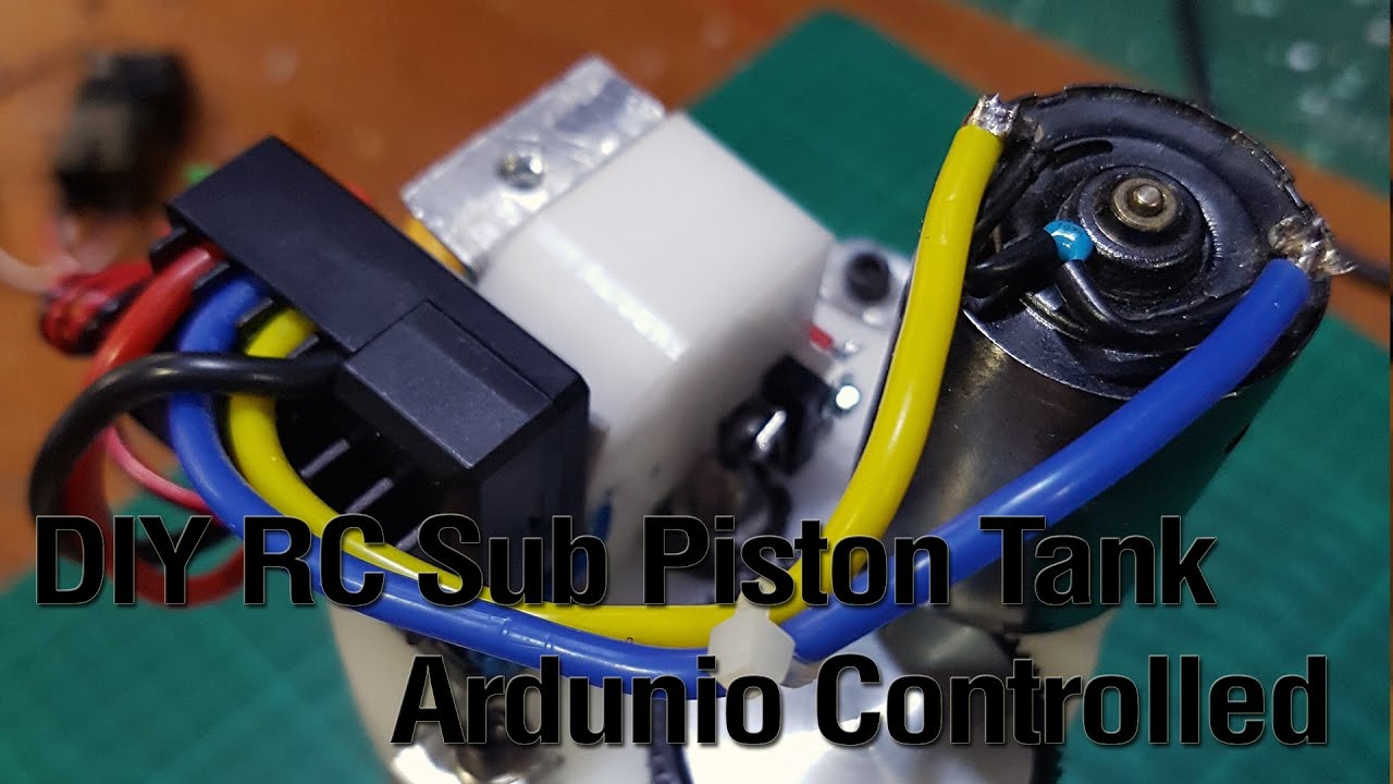
    A preview of how it looks in action (this tank does not use the trim function)


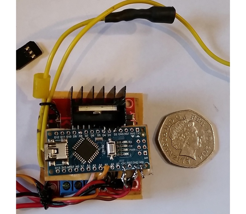
    The pins are configured in the code to allow installation of plug connectors on the arduino for secure connection and easy maintenance as shown below.
    Click image for larger version

Name:	Arduino.jpg
Views:	2
Size:	51.3 KB
ID:	136961
    Last edited by IdefixRC; 05-21-2017, 03:42 AM.
  • IdefixRC
    Junior Member
    • Apr 2017
    • 42

    #2
    Option 1 – H-Bridge:

    Follow the below wiring diagram and upload the code to the Arduino.
    Follow the ESC manual to set the full throttle, neutral and reverse endpoints.
    Carefully check that motor direction is correct and that endstops work (and are not swapped)
    Dive away…….

    Connections in a nutshell:

    Receiver:
    • Connect Receiver Signal Pin to Arduino Nano Pin A5
    • Connect Receiver GND Pin to Arduino Nano Pin GND
    • Connect Receiver 5V Pin to Arduino Nano Pin VCC


    H-Bridge:
    • Connect HBridge Motor Direction Pin 1 to Arduino Nano Pin D2
    • Connect HBridge Motor Enable Pin to Arduino Nano Pin D3
    • Connect HBridge Motor Direction Pin 2 to Arduino Nano Pin D4


    End Stops:
    • Connect Flood end stop Pin to Arduino Nano Pin D6
    • Connect Drain end stop to Arduino Nano Pin D7
    • Connect Trim end stop to Arduino Nano Pin D8
    • Note: All endstop switches are default open. Drain endstop need so close when depressed, Trim and Flood Endstops need to close when pressed.
    • Arduino Input pins connects to switch and via 10k pull up resistor to GND, 2nd switch leg connects to Arduino 5v Pin


    Wiring Diagram:
    Click image for larger version

Name:	Wiring_HBridge.jpg
Views:	1
Size:	92.8 KB
ID:	129996

    Comment

    • IdefixRC
      Junior Member
      • Apr 2017
      • 42

      #3
      Arduino Code - HBridge Version - Part 1:
      Split into 2 sections due to text limitations in the forum. Simply copy both code snippets below each other as shown here

      Code:
      /*
      Piston_Tank_Controller.ino
      
      RC Submarine Piston Tank controller based on Arduino Nano.
      HBridge Version
      
      created: 14 May 2017 by Eric Weber
      
      Circuit & Features:
      - Reads PWM Signal from RC Receiver on Arduino Nano Pin A5
      - Controls H-Bridge to drive DC motor to flood and drain piston tank - PWM value > 1600 drains tank, PWM value <1400 floods tank, Motor off @ PWM value 1600-1400
        - Connect Motor Direction Pin 1 to Arduino Nano Pin D2
        - Connect Motor Enable Pin to Arduino Nano Pin D3
        - Connect Motor Direction Pin 2 to Arduino Nano Pin D4
      
      - Piston tank motor speed can be adjusted by changing the RC endpoints as follows:
        - 2000-1900 & 1000-1100 = 100% speed
        - 1900-1800 & 1100-1200 = 90% speed
        - 1800-1700 & 1200-1300 = 80% speed
        
      Usage of 3 endstops as follows:
        - #1: Flood endstop connected to Arduino Nano Pin D6 - prevents motor from further flooding the piston tank when in open position
        - #2: Drain endstop connected to Arduino Nano Pin D7 - prevents motor from further draining the piston tank when in open position
        - #3: Trim endstop connected to Arduino Nano Pin D8 - stops the motor when in open position. PWM signal needs to be reset to neutral (1600-1400) to enable further motor movement
        - All endstop switches are default open. Drain endstop need so close when depressed, Trim and Flood Endstops need to close when pushed.Input pin connects to switch and via 10k pull up resistor to GND, 2nd switch leg connects to Arduino 5v Pin
        
      Automatic failsafe drain - tank is automatically drained when a PWM signal below 1000ms is found
      
      
      Requirements:
      - requires eRCaGuy_Timer2_Counter.h by Gabriel Staples. Download from http://www.electricrcaircraftguy.com/2014/02/Timer2Counter-more-precise-Arduino-micros-function.html
      
      Credits:
      - This sketch makes extensive use of code and libraries devleoped by Gabriel Staples @ http://www.ElectricRCAircraftGuy.com/
      - Button Debounce code based on example from http://www.arduino.cc/en/Tutorial/Debounce
      
      */
      
      
      #include <eRCaGuy_Timer2_Counter.h>
      
      // Start RC PWM definitions
        //macros
        #define fastDigitalRead(p_inputRegister, bitMask) ((*p_inputRegister & bitMask) ? HIGH : LOW)
        
        //Global Variables & defines for the RC PWM Read in portion
        const byte INPUT_PIN = A5;  // Arduino Nano Pin A5
                                    //PWM Input signal from RC receiver goes here. Can be changed to ANY digital or analog pin, ex: 10, 8, A0, A5, etc, 
                                    //EXCEPT A6 and A7 (which exists on the Nano and Pro Mini, for example, and are NOT capable of digital operations)
                                   
        byte input_pin_bitMask;
        volatile byte* p_input_pin_register;
        
        //volatile variables for use in the ISR (Interrupt Service Routine)
        volatile boolean output_data = false;     //the main loop will try to output data each time a new pulse comes in, which is when this gets set true
        volatile unsigned long pulseCounts = 0;   //units of 0.5us; the input signal high pulse time
        volatile unsigned int pd = 0;             //units of 0.5us; the pulse period (ie: time from start of high pulse to start of next high pulse)
      // End RC PWM definitions
      
      // Start Endstop definitions
        //Global Variables & defines for the End Stop portion
        const int StopFloodPin = 6;    // the number of the Flood Tank EndStop pin
        const int StopDrainPin = 7;    // the number of the Drain Tank EndStop pin
        const int TrimPin = 8;    // the number of the Trim Switch pin
        
        // Variables will change:
        int FloodState;             // the current reading from the Flood Endstop input pin
        int lastFloodState = LOW;   // the previous reading from the Flood Endstop input pin
        int DrainState;             // the current reading from the Drain Endstop input pin
        int lastDrainState = LOW;   // the previous reading from the Drain Endstop input pin
        int TrimState;             // the current reading from the Trim Switch input pin
        int lastTrimState = LOW;   // the previous reading from the Trim Switch input pin
        int TrimStop = HIGH;       // Trim Stop flag
        
        // the following variables are unsigned long's because the time, measured in miliseconds,
        // will quickly become a bigger number than can be stored in an int.
        unsigned long lastFloodDebounceTime = 0;  // the last time the output pin was toggled
        unsigned long debounceFloodDelay = 50;    // the debounce time; increase if the output flickers
        unsigned long lastDrainDebounceTime = 0;  // the last time the output pin was toggled
        unsigned long debounceDrainDelay = 50;    // the debounce time; increase if the output flickers
        unsigned long lastTrimDebounceTime = 0;  // the last time the output pin was toggled
        unsigned long debounceTrimDelay = 50;    // the debounce time; increase if the output flickers
      // End Endstop definitions
      
      // Start Motor definitions
        // Global Variables & defines for L298N Dual H-Bridge Motor Controller
        int dir1PinA = 2;  // Arduino Nano Pin 2
        int dir2PinA = 4;  // Arduino Nano Pin 4
        int speedPinA = 3; // Arduino Nano Pin 3 - Needs to be a PWM pin to be able to control motor speed
      // End Motor definitions
      
      void setup() 
      {
        // RC PWM Part Start
          pinMode(INPUT_PIN,INPUT_PULLUP);        //use INPUT_PULLUP to keep the pin from floating and jumping around when nothing is connected
        
          //configure timer2
          timer2.setup();
        
          //prepare for FAST digital reads on INPUT_PIN, by mapping to the input register (ex: PINB, PINC, or PIND), and creating a bitMask
          //using this method, digital reads are done in approx. 0.148us/reading, rather than using digitalRead, which takes 4.623us/reading (31x speed increase)
          input_pin_bitMask = digitalPinToBitMask(INPUT_PIN);
          p_input_pin_register = portInputRegister(digitalPinToPort(INPUT_PIN));
          
          configurePinChangeInterrupts();
        
          //print values 
          //Enable for Debugging
          //Serial.begin(115200);
          //Serial.print(F("Begin waiting for pulses on pin ")); Serial.print(INPUT_PIN);
          //Serial.println(F(".\nData will be printed after each pulse is received."));
        // RC PWM Part End
      
        // Endstop Part Start
          pinMode(StopFloodPin, INPUT);
          pinMode(StopDrainPin, INPUT);
          pinMode(TrimPin, INPUT);
        // Endstop Part End  
      
        //Motor Control Part Start
          //Define L298N Dual H-Bridge Motor Controller Pins
          pinMode(dir1PinA,OUTPUT);
          pinMode(dir2PinA,OUTPUT);
          pinMode(speedPinA,OUTPUT);
        //Motor Control Part End
      }
      
      void loop() 
      {
        // RC PWM Part Start
          //local variables
          static float pulseTime = 0;   //us; the most recent input signal high pulse time
          static float pd_us = 0;       //us; the most recent input signal period between pulses
          static float pulseFreq = 0;   //Hz, the most recent input signal pulse frequency
        // RC PWM Part End
      
        // Endstop Part Start
          // read the state of the switch into a local variable:
          int readingFlood = digitalRead(StopFloodPin);
          int readingDrain = digitalRead(StopDrainPin);
          int readingTrim = digitalRead(TrimPin);
       
          // check to see if you just pressed the button
          // (i.e. the input went from LOW to HIGH),  and you've waited
          // long enough since the last press to ignore any noise:
        
          // Flood Switch Code End
            // If the switch changed, due to noise or pressing:
            if (readingFlood != lastFloodState) {
              // reset the debouncing timer
              lastFloodDebounceTime = millis();
            }
          
            if ((millis() - lastFloodDebounceTime) > debounceFloodDelay) {
              // whatever the reading is at, it's been there for longer
              // than the debounce delay, so take it as the actual current state:
          
              // if the button state has changed:
              if (readingFlood != FloodState) {
                FloodState = readingFlood;         
              }
            }
          // Flood Switch Code End
      
          // Drain Switch Code End
            // If the switch changed, due to noise or pressing:
            if (readingDrain != lastDrainState) {
              // reset the debouncing timer
              lastDrainDebounceTime = millis();
            }
          
            if ((millis() - lastDrainDebounceTime) > debounceDrainDelay) {
              // whatever the reading is at, it's been there for longer
              // than the debounce delay, so take it as the actual current state:
          
              // if the button state has changed:
              if (readingDrain != DrainState) {
                DrainState = readingDrain;         
              }
            }
          // Drain Switch Code End
      
          // Trim Switch Code End
            // If the switch changed, due to noise or pressing:
            if (readingTrim != lastTrimState) {
              // reset the debouncing timer
              lastTrimDebounceTime = millis();
            }
          
            if ((millis() - lastTrimDebounceTime) > debounceTrimDelay) {
              // whatever the reading is at, it's been there for longer
              // than the debounce delay, so take it as the actual current state:
                      
              // if the button state has changed:
              if (readingTrim != TrimState) {
                TrimState = readingTrim;        
                  
                  if (lastTrimState == HIGH){       // Set TrimStop to HIGH if reading changed from low to high - button pressed
                    TrimStop = HIGH;          
                  }
                  
                }
            }
          // Trim Switch Code End
      
        // Endstop Part End
      Last edited by IdefixRC; 05-21-2017, 03:34 AM.

      Comment

      • IdefixRC
        Junior Member
        • Apr 2017
        • 42

        #4
        Arduino Code - HBridge Version - Part 2:
        Split into 2 sections due to text limitations in the forum. Simply copy both code snippets below each other as shown here

        Code:
          //Motor Control Part Start
            //local variables
            int MotoDir = 2;     //Motor Direction Indicator
          //Motor Control Part End
        
          // RC PWM Part Start
          if (output_data==true) //if a pulse just came in
          {
            //turn off interrupts, grab copies of volatile data, and re-enable interrupts
            noInterrupts();
            output_data = false; //reset
            unsigned long pulseCountsCopy = pulseCounts; //0.5us units
            unsigned long pdCopy = pd; //0.5us units
            interrupts();
            
            //do calculations
            pulseTime = pulseCountsCopy/2.0; //us
            pd_us = pdCopy/2.0; //us
            pulseFreq = 1000000.0/pd_us; //Hz
            
            //print values 
            //Enable for Debugging
            //Serial.print(F("pulsetime(us) = ")); Serial.print(pulseTime);
            //Serial.print(F(", pd_us(us) = ")); Serial.print(pd_us);
            //Serial.print(F(", pulseFreq(Hz) = ")); Serial.println(pulseFreq);
          // RC PWM Part Start
        
         // Motor Control Start
            // Check Motor Direction
            // if (pulseTime > 1600 && pulseTime < 1600) 
            if ((pulseTime > 1600 && DrainState != HIGH && TrimStop != HIGH)||(pulseTime < 1000 && DrainState != HIGH ) ) 
               {
                // Motor Forward (Drain Tank) 
                int speed = pulseTime / 100;
                speed = map(speed, 16, 20, 178, 255); // map speed based on input PWM value
        
                // overwrites speed variable in case of failsafe
                if (pulseTime <1000)
                 {
                  speed = 255;
                 }
                
                analogWrite(speedPinA, speed);//Sets speed variable via PWM 
                digitalWrite(dir1PinA, LOW);
                digitalWrite(dir2PinA, HIGH);
        
                //print values 
                //Enable for Debugging
                //Serial.println("Motor Forward - Drain Tank");   // Prints out “Motor Forward - Drain Tank” on the serial monitor
                //Serial.println(speed);                          // Prints out motor speed setting on the serial monitor
                //Serial.println(TrimStop);                       // Prints out status of the trim switch
                //Serial.println("   ");                          // Creates a blank line printed on the serial monitor
              }
            else
            {
              if (pulseTime < 1400 && FloodState != HIGH && TrimStop != HIGH)
              {
                // Motor Forward (Flood Tank) 
                int speed = pulseTime / 100;
                speed = map(speed, 14, 10, 178, 255); // map speed based on input PWM value
                analogWrite(speedPinA, 255);
                digitalWrite(dir1PinA, HIGH);
                digitalWrite(dir2PinA, LOW);
                
                //print values 
                //Enable for Debugging
                //Serial.println("Motor Reverse - Flood Tank");   // Prints out “Motor Reverse - Flood Tank” on the serial monitor
                //Serial.println(speed);                          // Prints out motor speed setting on the serial monitor
                //Serial.println(TrimStop);                       // Prints out status of the trim switch
                //Serial.println("   ");                          // Creates a blank line printed on the serial monitor
              }
              else
              {
              // Motor Stop (Neutral Position)
              if (pulseTime <= 1600 && pulseTime >= 1400){
                TrimStop = LOW;                                 // Resets TrimStop to Low  
              }
              analogWrite(speedPinA, 0);
              digitalWrite(dir1PinA, LOW);
              digitalWrite(dir2PinA, HIGH);
              
              //print values 
              //Enable for Debugging
              //Serial.println("Motor Stop");                 // Prints out “Motor Stop” on the serial monitor
              //Serial.println(TrimStop);                     // Prints out status of the trim switch
              //Serial.println("   ");                        // Creates a blank line printed on the serial monitor
              }
            }
         // Motor Control End
            
           }
        
        // save the Endstop reading.  Next time through the loop,
        // it'll be the lastButtonState:
        lastFloodState = readingFlood;
        lastDrainState = readingDrain;
        lastTrimState = readingTrim;
        
        } //end of loop()
        
        
        void pinChangeIntISR()
        {
          //local variables
          static boolean pin_state_new = LOW; //initialize
          static boolean pin_state_old = LOW; //initialize
          static unsigned long t_start = 0; //units of 0.5us
          static unsigned long t_start_old = 0; //units of 0.5us
          
          pin_state_new = fastDigitalRead(p_input_pin_register,input_pin_bitMask);
          if (pin_state_old != pin_state_new)
          {
            //if the pin state actualy changed, & it was not just noise lasting < ~2~4us
            pin_state_old = pin_state_new; //update the state
            if (pin_state_new == HIGH)
            {
              t_start = timer2.get_count(); //0.5us units
              pd = t_start - t_start_old; //0.5us units, the incoming pulse period
              t_start_old = t_start; //0.5us units; update
            }
            else //pin_state_new == LOW
            {
              unsigned long t_end = timer2.get_count(); //0.5us units
              pulseCounts = t_end - t_start; //0.5us units
              output_data = true;
            }
          }
        }
        
        //Interrupt Service Routines (ISRs) for Pin Change Interrupts
        //see here: http://www.gammon.com.au/interrupts
        
        //PCINT0_vect is for pins D8 to D13
        ISR(PCINT0_vect)
        {
          pinChangeIntISR();
        }
        
        //PCINT1_vect is for pins A0 to A5
        ISR(PCINT1_vect)
        {
          pinChangeIntISR();
        }
        
        //PCINT2_vect is for pins D0 to D7
        ISR(PCINT2_vect)
        {
          pinChangeIntISR();
        }
        
        void configurePinChangeInterrupts()
        {
          //Pin Change Interrupt Configuration
          //see ATmega328 datasheet, ex: pgs. 73-75
          //also see: C:\Program Files (x86)\Arduino\hardware\arduino\avr\variants\standard\pins_arduino.h for the macros used here
          //1st, set flags on the proper Pin Change Mask Register (PCMSK)
          volatile byte* p_PCMSK = (volatile byte*)digitalPinToPCMSK(INPUT_PIN); //pointer to the proper PCMSK register
          *p_PCMSK = _BV(digitalPinToPCMSKbit(INPUT_PIN));
          
          //2nd, set flags in the Pin Change Interrupt Control Register (PCICR)
          volatile byte* p_PCICR = (volatile byte*)digitalPinToPCICR(INPUT_PIN); //pointer to PCICR
          *p_PCICR |= _BV(digitalPinToPCICRbit(INPUT_PIN));
          
        //  //ex: to use digital pin 8 as the INPUT_PIN:
        //  //turn on PCINT0_vect Pin Change Interrupts (for pins D8 to D13); see datasheet pg. 73-75.
        //  //1st, set flags on the proper Pin Change Mask Register
        //  PCMSK0 = 0b00000001; //here I am setting Bit0 to a 1, to mark pin D8's pin change register as on; for pin mapping see here: http://arduino.cc/en/Hacking/PinMapping168
        //  //2nd, set flags in the Pin Change Interrupt Control Register
        //  PCICR |= 0b00000001; //here I am turning on the pin change vector 0 interrupt, for PCINT0_vect, by setting the right-most bit to a 1
        }
        Last edited by IdefixRC; 05-21-2017, 03:33 AM.

        Comment

        • IdefixRC
          Junior Member
          • Apr 2017
          • 42

          #5
          Option 2 – ESC:
          Follow the below wiring diagram and upload the code to the Arduino.
          Follow the ESC manual to set the full throttle, neutral and reverse endpoints.
          Carefully check that motor direction is correct and that endstops work (and are not swapped)
          Dive away…….

          Connections in a nutshell:
          Receiver:
          • Connect Receiver Signal Pin to Arduino Nano Pin A5
          • Connect Receiver GND Pin to Arduino Nano Pin GND
          • Connect Receiver 5V Pin to Arduino Nano Pin VCC


          Speed Controller / ESC:
          • Connect ESC Signal Pin to Arduino Nano Pin D3
          • Connect ESC GND Pin to Arduino Nano Pin GND
          • Connect ESC 5V Pin to Arduino Nano Pin 5V (NOTE: only required if the ESC does not have a UBEC – opto ESC – or if you want to power the RC receiver and Arduino from the piston tank UBEC – do NOT connect 2x 5V from Sub drive motor & piston tank to the same circuit)


          End Stops:
          • Connect Flood end stop Pin to Arduino Nano Pin D6
          • Connect Drain end stop to Arduino Nano Pin D7
          • Connect Trim end stop to Arduino Nano Pin D8
          • Note: All endstop switches are default open. Drain endstop need so close when depressed, Trim and Flood Endstops need to close when pressed. Arduino Input pins connects to switch and via 10k pull up resistor to GND, 2nd switch leg connects to Arduino 5v Pin


          Wiring Diagram:
          Click image for larger version

Name:	Wiring_ESC.jpg
Views:	1
Size:	88.8 KB
ID:	129997

          Comment

          • IdefixRC
            Junior Member
            • Apr 2017
            • 42

            #6
            Arduino Code - ESC Speed Controller version- Part 1:
            Split into 2 sections due to text limitations in the forum. Simply copy both code snippets below each other as shown here

            Code:
            /*
            Piston_Tank_Controller_V2.ino
            
            RC Submarine Piston Tank controller based on Arduino Nano.
            ESC/Speed Controller Version
            
            created: 20 May 2017 by Eric Weber
            
            Circuit & Features:
            - Reads PWM Signal from RC Receiver on Arduino Nano Pin A5
            - Controls brush or brushless ESC to drive piston tank motor to flood and drain piston tank - PWM value > 1600 drains tank, PWM value <1400 floods tank, Motor off @ PWM value 1600-1400
              - Connect ESC Signal Pin to Arduino Nano Pin D3
              - Connect ESC GND to Arduino GND
              - Connect ESC 5V to Arduino 5V
            
            - Piston tank motor speed can be adjusted by changing the RC endpoints as follows:
              - 2000-1800 & 1000-1200 = 100% speed
              - 1800-1700 & 1200-1300 = 85% speed
              - 1800-1700 & 1200-1300 = 65% speed
            
              
            Usage of 3 endstops as follows:
              - #1: Flood endstop connected to Arduino Nano Pin D6 - prevents motor from further flooding the piston tank when in open position
              - #2: Drain endstop connected to Arduino Nano Pin D7 - prevents motor from further draining the piston tank when in open position
              - #3: Trim endstop connected to Arduino Nano Pin D8 - stops the motor when in open position. PWM signal needs to be reset to neutral (1600-1400) to enable further motor movement
              - All endstop switches are default open. Drain endstop need so close when depressed, Trim and Flood Endstops need to close when pushed.Input pin connects to switch and via 10k pull up resistor to GND, 2nd switch leg connects to Arduino 5v Pin
              
            Automatic failsafe drain - tank is automatically drained when a PWM signal below 1000ms is found
            
            
            Requirements:
            - requires eRCaGuy_Timer2_Counter.h by Gabriel Staples. Download from http://www.electricrcaircraftguy.com/2014/02/Timer2Counter-more-precise-Arduino-micros-function.html
            - Arduino Servo Library
            
            Credits:
            - This sketch makes extensive use of code and libraries devleoped by Gabriel Staples @ http://www.ElectricRCAircraftGuy.com/
            - Button Debounce code based on example from http://www.arduino.cc/en/Tutorial/Debounce
            
            */
            
            
            #include <eRCaGuy_Timer2_Counter.h>
            #include <Servo.h>
            
            // Start RC PWM definitions
              //macros
              #define fastDigitalRead(p_inputRegister, bitMask) ((*p_inputRegister & bitMask) ? HIGH : LOW)
              
              //Global Variables & defines for the RC PWM Read in portion
              const byte INPUT_PIN = A5;  // Arduino Nano Pin A5
                                          //PWM Input signal from RC receiver goes here. Can be changed to ANY digital or analog pin, ex: 10, 8, A0, A5, etc, 
                                          //EXCEPT A6 and A7 (which exists on the Nano and Pro Mini, for example, and are NOT capable of digital operations)
                                         
              byte input_pin_bitMask;
              volatile byte* p_input_pin_register;
              
              //volatile variables for use in the ISR (Interrupt Service Routine)
              volatile boolean output_data = false;     //the main loop will try to output data each time a new pulse comes in, which is when this gets set true
              volatile unsigned long pulseCounts = 0;   //units of 0.5us; the input signal high pulse time
              volatile unsigned int pd = 0;             //units of 0.5us; the pulse period (ie: time from start of high pulse to start of next high pulse)
            // End RC PWM definitions
            
            // Start Endstop definitions
              //Global Variables & defines for the End Stop portion
              const int StopFloodPin = 6;    // the number of the Flood Tank EndStop pin
              const int StopDrainPin = 7;    // the number of the Drain Tank EndStop pin
              const int TrimPin = 8;    // the number of the Trim Switch pin
              
              // Variables will change:
              int FloodState;             // the current reading from the Flood Endstop input pin
              int lastFloodState = LOW;   // the previous reading from the Flood Endstop input pin
              int DrainState;             // the current reading from the Drain Endstop input pin
              int lastDrainState = LOW;   // the previous reading from the Drain Endstop input pin
              int TrimState;             // the current reading from the Trim Switch input pin
              int lastTrimState = LOW;   // the previous reading from the Trim Switch input pin
              int TrimStop = HIGH;       // Trim Stop flag
              
              // the following variables are unsigned long's because the time, measured in miliseconds,
              // will quickly become a bigger number than can be stored in an int.
              unsigned long lastFloodDebounceTime = 0;  // the last time the output pin was toggled
              unsigned long debounceFloodDelay = 50;    // the debounce time; increase if the output flickers
              unsigned long lastDrainDebounceTime = 0;  // the last time the output pin was toggled
              unsigned long debounceDrainDelay = 50;    // the debounce time; increase if the output flickers
              unsigned long lastTrimDebounceTime = 0;  // the last time the output pin was toggled
              unsigned long debounceTrimDelay = 50;    // the debounce time; increase if the output flickers
            // End Endstop definitions
            
            // Start ESC definitions
              Servo pistonesc;
              
              // Variables will change:
              int drspeed = 90;             // ESC drain position and speed
              int flspeed = 90;            // ESC flood position and speed
              
            // End ESC definitions
            
            void setup() 
            {
              // RC PWM Part Start
                pinMode(INPUT_PIN,INPUT_PULLUP);        //use INPUT_PULLUP to keep the pin from floating and jumping around when nothing is connected
              
                //configure timer2
                timer2.setup();
              
                //prepare for FAST digital reads on INPUT_PIN, by mapping to the input register (ex: PINB, PINC, or PIND), and creating a bitMask
                //using this method, digital reads are done in approx. 0.148us/reading, rather than using digitalRead, which takes 4.623us/reading (31x speed increase)
                input_pin_bitMask = digitalPinToBitMask(INPUT_PIN);
                p_input_pin_register = portInputRegister(digitalPinToPort(INPUT_PIN));
                
                configurePinChangeInterrupts();
              
                //print values 
                //Enable for Debugging
                //Serial.begin(115200);
                //Serial.print(F("Begin waiting for pulses on pin ")); Serial.print(INPUT_PIN);
                //Serial.println(F(".\nData will be printed after each pulse is received."));
              // RC PWM Part End
            
              // Endstop Part Start
                pinMode(StopFloodPin, INPUT);
                pinMode(StopDrainPin, INPUT);
                pinMode(TrimPin, INPUT);
              // Endstop Part End  
            
              //ESC Control Part Start
                //Define ESC Signal Pin
                pistonesc.attach(3);
                pistonesc.write(90);  // set ESC to mid-point - STOP
              //Motor Control Part End
            }
            
            void loop() 
            {
              // RC PWM Part Start
                //local variables
                static float pulseTime = 0;   //us; the most recent input signal high pulse time
                static float pd_us = 0;       //us; the most recent input signal period between pulses
                static float pulseFreq = 0;   //Hz, the most recent input signal pulse frequency
              // RC PWM Part End
            
              // Endstop Part Start
                // read the state of the switch into a local variable:
                int readingFlood = digitalRead(StopFloodPin);
                int readingDrain = digitalRead(StopDrainPin);
                int readingTrim = digitalRead(TrimPin);
             
                // check to see if you just pressed the button
                // (i.e. the input went from LOW to HIGH),  and you've waited
                // long enough since the last press to ignore any noise:
              
                // Flood Switch Code End
                  // If the switch changed, due to noise or pressing:
                  if (readingFlood != lastFloodState) {
                    // reset the debouncing timer
                    lastFloodDebounceTime = millis();
                  }
                
                  if ((millis() - lastFloodDebounceTime) > debounceFloodDelay) {
                    // whatever the reading is at, it's been there for longer
                    // than the debounce delay, so take it as the actual current state:
                
                    // if the button state has changed:
                    if (readingFlood != FloodState) {
                      FloodState = readingFlood;         
                    }
                  }
                // Flood Switch Code End
            
                // Drain Switch Code End
                  // If the switch changed, due to noise or pressing:
                  if (readingDrain != lastDrainState) {
                    // reset the debouncing timer
                    lastDrainDebounceTime = millis();
                  }
                
                  if ((millis() - lastDrainDebounceTime) > debounceDrainDelay) {
                    // whatever the reading is at, it's been there for longer
                    // than the debounce delay, so take it as the actual current state:
                
                    // if the button state has changed:
                    if (readingDrain != DrainState) {
                      DrainState = readingDrain;         
                    }
                  }
                // Drain Switch Code End
            
                // Trim Switch Code End
                  // If the switch changed, due to noise or pressing:
                  if (readingTrim != lastTrimState) {
                    // reset the debouncing timer
                    lastTrimDebounceTime = millis();
                  }
                
                  if ((millis() - lastTrimDebounceTime) > debounceTrimDelay) {
                    // whatever the reading is at, it's been there for longer
                    // than the debounce delay, so take it as the actual current state:
                            
                    // if the button state has changed:
                    if (readingTrim != TrimState) {
                      TrimState = readingTrim;        
                        
                        if (lastTrimState == HIGH){       // Set TrimStop to HIGH if reading changed from low to high - button pressed
                          TrimStop = HIGH;          
                        }
                        
                      }
                  }
                // Trim Switch Code End
            
              // Endstop Part End

            Comment

            • IdefixRC
              Junior Member
              • Apr 2017
              • 42

              #7
              Arduino Code - ESC Speed Controller version- Part 2:
              Split into 2 sections due to text limitations in the forum. Simply copy both code snippets below each other as shown here

              Code:
                // RC PWM Part Start
                if (output_data==true) //if a pulse just came in
                {
                  //turn off interrupts, grab copies of volatile data, and re-enable interrupts
                  noInterrupts();
                  output_data = false; //reset
                  unsigned long pulseCountsCopy = pulseCounts; //0.5us units
                  unsigned long pdCopy = pd; //0.5us units
                  interrupts();
                  
                  //do calculations
                  pulseTime = pulseCountsCopy/2.0; //us
                  pd_us = pdCopy/2.0; //us
                  pulseFreq = 1000000.0/pd_us; //Hz
                  
                  //print values 
                  //Enable for Debugging
                  //Serial.print(F("pulsetime(us) = ")); Serial.print(pulseTime);
                  //Serial.print(F(", pd_us(us) = ")); Serial.print(pd_us);
                  //Serial.print(F(", pulseFreq(Hz) = ")); Serial.println(pulseFreq);
                // RC PWM Part Start
              
               // Motor Control Start
                     
                  if ((pulseTime > 1600 && DrainState != HIGH && TrimStop != HIGH)||(pulseTime < 1000 && DrainState != HIGH ) ) 
                     {
                      // Motor Forward (Drain Tank) 
                      // overwrites speed variable in case of failsafe
                      if (pulseTime <1000)
                       {
                        drspeed = 1900;
                       }
              
                      // Set Drain Speed (the ugly way)
                      if (pulseTime >1600 && pulseTime <=1700)
                       {
                        drspeed = 1760;
                       }
                       if (pulseTime >1700 && pulseTime <=1800)
                       {
                        drspeed = 1840;
                       }
                       if (pulseTime >1800)
                       {
                        drspeed = 1900;
                       }
                      
                      pistonesc.writeMicroseconds(drspeed);
              
                      //print values 
                      //Enable for Debugging
                      //Serial.println("Motor Forward - Drain Tank");   // Prints out “Motor Forward - Drain Tank” on the serial monitor
                      //Serial.println(drspeed);                          // Prints out motor speed setting on the serial monitor
                      //Serial.println(TrimStop);                       // Prints out status of the trim switch
                      //Serial.println("   ");                          // Creates a blank line printed on the serial monitor
                    }
                  else
                  {
                    if (pulseTime < 1400 && FloodState != HIGH && TrimStop != HIGH)
                    {
                      // Motor Forward (Flood Tank) 
              
                      // Set Flood Speed (the ugly way)
                      if (pulseTime <1400 && pulseTime >=1300)
                       {
                        flspeed = 1100;
                       }
                       if (pulseTime <1300 && pulseTime >=1200)
                       {
                        flspeed = 1160;
                       }
                       if (pulseTime <1200)
                       {
                        flspeed = 1240;
                       }
                           
                      pistonesc.writeMicroseconds(flspeed);
                      
                      //print values 
                      //Enable for Debugging
                      //Serial.println("Motor Reverse - Flood Tank");   // Prints out “Motor Reverse - Flood Tank” on the serial monitor
                      //Serial.println(flspeed);                          // Prints out motor speed setting on the serial monitor
                      //Serial.println(TrimStop);                       // Prints out status of the trim switch
                      //Serial.println("   ");                          // Creates a blank line printed on the serial monitor
                    }
                    else
                    {
                    // Motor Stop (Neutral Position)
                      if (pulseTime <= 1600 && pulseTime >= 1400){
                        TrimStop = LOW;                                 // Resets TrimStop to Low  
                      }
                    
                    pistonesc.writeMicroseconds(1500);
                    
                    //print values 
                    //Enable for Debugging
                    //Serial.println("Motor Stop");                 // Prints out “Motor Stop” on the serial monitor
                    //Serial.println(TrimStop);                     // Prints out status of the trim switch
                    //Serial.println("   ");                        // Creates a blank line printed on the serial monitor
                    }
                  }
               // Motor Control End
                  
                 }
              
              // save the Endstop reading.  Next time through the loop,
              // it'll be the lastButtonState:
              lastFloodState = readingFlood;
              lastDrainState = readingDrain;
              lastTrimState = readingTrim;
              
              } //end of loop()
              
              
              void pinChangeIntISR()
              {
                //local variables
                static boolean pin_state_new = LOW; //initialize
                static boolean pin_state_old = LOW; //initialize
                static unsigned long t_start = 0; //units of 0.5us
                static unsigned long t_start_old = 0; //units of 0.5us
                
                pin_state_new = fastDigitalRead(p_input_pin_register,input_pin_bitMask);
                if (pin_state_old != pin_state_new)
                {
                  //if the pin state actualy changed, & it was not just noise lasting < ~2~4us
                  pin_state_old = pin_state_new; //update the state
                  if (pin_state_new == HIGH)
                  {
                    t_start = timer2.get_count(); //0.5us units
                    pd = t_start - t_start_old; //0.5us units, the incoming pulse period
                    t_start_old = t_start; //0.5us units; update
                  }
                  else //pin_state_new == LOW
                  {
                    unsigned long t_end = timer2.get_count(); //0.5us units
                    pulseCounts = t_end - t_start; //0.5us units
                    output_data = true;
                  }
                }
              }
              
              //Interrupt Service Routines (ISRs) for Pin Change Interrupts
              //see here: http://www.gammon.com.au/interrupts
              
              //PCINT0_vect is for pins D8 to D13
              ISR(PCINT0_vect)
              {
                pinChangeIntISR();
              }
              
              //PCINT1_vect is for pins A0 to A5
              ISR(PCINT1_vect)
              {
                pinChangeIntISR();
              }
              
              //PCINT2_vect is for pins D0 to D7
              ISR(PCINT2_vect)
              {
                pinChangeIntISR();
              }
              
              void configurePinChangeInterrupts()
              {
                //Pin Change Interrupt Configuration
                //see ATmega328 datasheet, ex: pgs. 73-75
                //also see: C:\Program Files (x86)\Arduino\hardware\arduino\avr\variants\standard\pins_arduino.h for the macros used here
                //1st, set flags on the proper Pin Change Mask Register (PCMSK)
                volatile byte* p_PCMSK = (volatile byte*)digitalPinToPCMSK(INPUT_PIN); //pointer to the proper PCMSK register
                *p_PCMSK = _BV(digitalPinToPCMSKbit(INPUT_PIN));
                
                //2nd, set flags in the Pin Change Interrupt Control Register (PCICR)
                volatile byte* p_PCICR = (volatile byte*)digitalPinToPCICR(INPUT_PIN); //pointer to PCICR
                *p_PCICR |= _BV(digitalPinToPCICRbit(INPUT_PIN));
                
              //  //ex: to use digital pin 8 as the INPUT_PIN:
              //  //turn on PCINT0_vect Pin Change Interrupts (for pins D8 to D13); see datasheet pg. 73-75.
              //  //1st, set flags on the proper Pin Change Mask Register
              //  PCMSK0 = 0b00000001; //here I am setting Bit0 to a 1, to mark pin D8's pin change register as on; for pin mapping see here: http://arduino.cc/en/Hacking/PinMapping168
              //  //2nd, set flags in the Pin Change Interrupt Control Register
              //  PCICR |= 0b00000001; //here I am turning on the pin change vector 0 interrupt, for PCINT0_vect, by setting the right-most bit to a 1
              }

              Comment

              • David F
                SubCommittee Member
                • Jan 2016
                • 60

                #8
                Thanks very much for posting all the details, Eric!

                It would be nice to know if anyone has picked this up and "run" with it?

                As a fellow developer of piston tank control systems, we often seem to post stuff up only to be faced with a deafening silence.

                I suppose it is because, even on a world basis, only a handful of people actually DO this kind of thing? (Lot's of people talk about it!)

                Anyway thanks again and let's hope you have started something.

                David

                Comment

                • bob_eissler
                  SubCommittee Member
                  • Aug 2005
                  • 331

                  #9
                  This is fascinating, I have an idea for a piston tank as well. Maybe there will be time to work on it this winter.

                  Comment

                  • bob_eissler
                    SubCommittee Member
                    • Aug 2005
                    • 331

                    #10
                    I'm really surprised at how fast and easily the piston moves in the video. What's the gear reduction are you using and the size and voltage of your motor?

                    Comment

                    • David F
                      SubCommittee Member
                      • Jan 2016
                      • 60

                      #11
                      Just to say that your sketch is working very nicely on the "bench" here using a nano.

                      I'm only using LEDs so far without the H Bridge.

                      Thanks for making your code available.

                      David

                      Comment

                      • David F
                        SubCommittee Member
                        • Jan 2016
                        • 60

                        #12
                        The H bridge modules have just arrived (from China) and I have just been trying them on my largest piston tank which displaces about a pint of water and draws a couple of amps. It works fine.
                        The ebay seller was a little bit short of information and this link is helpful:


                        Thanks again for this project.

                        David

                        Comment

                        • David F
                          SubCommittee Member
                          • Jan 2016
                          • 60

                          #13
                          Hi Eric,

                          I'm pleased to say that I now have a version of your hardware and software working giving proportional control using a Hall switch.

                          A short video showing the controller working with a home made piston tank built for my Nordenfelt subs is here:

                          Proportional control of piston tank for r/c model submarine using an Arduino Nano and a Hall switch.


                          The software is best downloaded from my site on Github (my first attempts at this so excuse me):

                          Proportional control of a piston tank for model submarines - rdforrest/submarine-proportional-pistontank


                          Some health warnings for anyone having a go, this version has only worked on the bench, not yet in a model submarine. So use it at your own risk.

                          I have also started a thread on this on the Association of Model Submariner's Forum:
                          Just done a bit more work on this inspired by Eric Weber's work on the SubCommittee Forum. Eric's hardware choice works nicely and it is ready built from an eB


                          Thanks for your inspiration for this. It was good to have suggested hardware which is "off the shelf". I think a lot of people are put off having to use a soldering iron!

                          David

                          Comment

                          • Ivcarlo
                            Junior Member
                            • Mar 2018
                            • 11

                            #14
                            Hi guys,
                            many compliments to Idefix for the piston tank control system.
                            Still i am not tried to program Arduino and i would like to start with this project but now i am at the beginning. I have to choose a model of submarine and i would like to ask something.
                            Also it will be my very first RC sub model.

                            Please how can i build the tank like the big syringe? Are there some tutorials?
                            For me how to build it it's an important thing to know because i have to get materials first.
                            Then dimensions of the tanks dictate the dimensions and scale of the model i will choose.

                            Thanks very much for every help!
                            Ivan

                            Comment

                            • IdefixRC
                              Junior Member
                              • Apr 2017
                              • 42

                              #15
                              Hi guys,

                              Sorry for the long silence. The project unfortunately had to take a step back due to personal circumstances.
                              Hope to be able to get back to this soon (the sub is still work in progress :-( ).

                              cheers,
                              Eric

                              Comment

                              Working...
                              X