
Hi all. Just thought I'd post some pics of a toy I made for myself, some time ago. It's basically an adjustable wooden stand, which holds an ordinary hardware store style device, which creates a visible line using a laser's beam. The base of the laser unit came with a way to rotate the device on its axis (to turn it clockwise or counter-clockwise) ... and I made a wooden deal which allowed me to make the line face horizontally or vertically. Or you can angle things around to "throw" a laser-straight line, at any angle you're likely to need such a line.
Here's a picture of the device itself, from when I first made it, and was trying it out. (Note I'm still using bolts; not threaded rod. I later found out that using wingnuts on both sides is a big improvement ... but for initial testing purposes, regular bolts worked okay.)
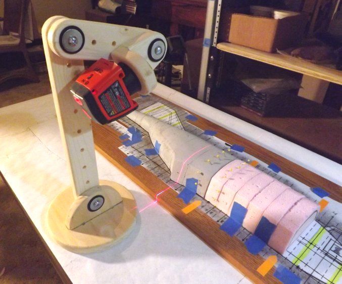
... and here's some pics of the thing, in actual use. (Pardon the non-submarine example uses! At least it's a flying boat!)

Not very exciting uses, probably (?) ... but you likely get the basic idea, of why / how it would be useful. And the laser unit itself is pretty cheap, at random hardware stores. And the base for it is just scrap pine (or plywood, or ...) and some "quarter twenty" rods cut to length (to put fasteners on both sides -- it's more easily tightened firmly, that way); and some rubber fender washers (for a bit of added squeeze, when positioning it; without damaging anything) and some metal fender washers, along with some wingnuts.
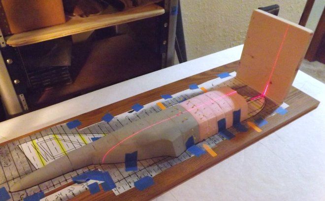
After having had this thing kicking around my shop for some time, I'd say my probably-favorite-so-far or "fun" type of use for it is to align the beam with some feature marked out on a 2D drawing (say a vertical hatch line) while a half-model isn't sitting on the 2D plans; and then place the model onto the plans, without moving anything. Assuming you have the unit casting a "right angle" beam, and it's not "leaning" one way or another, the laser easily projects that datum line, right where it needs to be. (The pic above shows me using a 90-degree set-up I had made, for parts-sanding purposes, to double-check the beam's squareness.) Move the (in this case, half-) model off of the 2D plans; align the laser with the other vertical edge of the hatch (simply by picking the whole unit up and moving it); replace the half-model on the plans; and mark that new or additional line.
Do the same basic thing for the horizontal lines which intersect with the vertical edges of that same feature, and in a matter of minutes, you have perfectly-located hatches -- (or whatever item you're marking off) -- even if your surface is contoured, etc.
Or you can do the same thing more efficiently. You can pre-mark those datum points or lines onto something like card stock, first ... and once you have them marked, onto taped-down card stock or index card or whatever, you carefully place the model over the plans, and then you can leave the model where it is, the whole time. You just align the forward and rear parts of the laser's line with the extended datum lines, as shown on the (taped down) card stock or whatever. And it'll "find" the spots on the model.
Not immediately visible, from these pics: I'm using a certain kind of marking pencil that's popular with pinstripers. Water-based. If you don't leave it on a surface too long, water will smudge it right back off -- making it easy to erase, if you need to move stuff. If you're careful, you won't need to. I mainly use 'em in instances like this, since they're softer, and won't "dent" foam model parts.

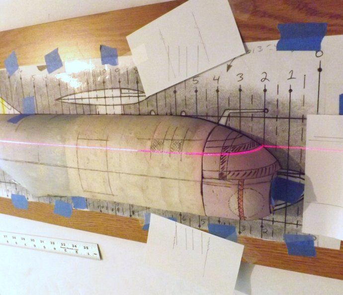
Because I'm cheap, whenever I can be, I re-used the index cards seen above. After they'd allowed me to mark the vertical hatch lines onto the model, I couldn't see any point in throwing those cards away ... so I just scribbled those lines out, as it were ... and turned those cards at an angle (so I wouldn't confused the old markings with any new ones I'd make) ... and taped them down, in a new spot (to mark off the vertical lines for the forward windows, along the plane's forward fuselage) ... and drew "window lines". (The two small square windows, located between the hatch or door in the side, and the main cockpit glass. See 'em?)
Here's a more recent pic of the device, after a bit of a mild beauty treatment. (Some wood stain and polyurethane clear, etc.)
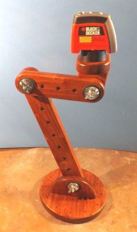
I don't think I have super-new pics of this unit. I'll have to take some, at some point. One big modification I made to the original design was to drill and tap several vertical holes, all around the base; made to fit quarter-twenty thumbscrews. You can see the holes, but the thumbscrews haven't been inserted yet, in the pic above.
The purpose there being to make "adjustable feet". In practice, it allows me to put the device onto irregular surfaces, and to be able to make almost "vernier" adjustments to line angle and so forth. Which also helps if you're really picky about having the line dead vertical or dead horizontal, or whatever. (For model usage, you should be ... but for some home tasks, it may be overkill.)
In practice, I just back all the thumbscrews off, at first, so they're recessed into the base. Then, turn the unit on, and look at which way the beam is not at right angles (leaning left or right, for instance) ... and move only the one screw that will "tilt" the unit (and thus, the beam it's casting) in the most helpful direction ... and then, any others that look like they'd help ... and once it's all perfectly square, then you can move enough other thumbscrews nearby, to make the whole base more wobble resistant.
An extreme-ish example of why I'd want so many thumbscrews located in the base, would be if a person were adding a tinted strip to their car's windshield; and wanted to use the laser to make a perfectly straight horizontal line on the windshield. Lay a cloth or something on the vehicle's hood (in this example) so you won't scratch the paint if the unit gets bumped ... and just turn the various "feet" back and forth, until you have the line the way you want it. Thus making the unit stable, even on that surface.
Great for many other household "home improvement" type chores, too! (Cutting overly-long curtains all nice and straight, before someone who knows how to sew could hem them up ... as just one practical example I've actually done. Did that one with the unit sitting in the middle of the room, on a contoured wooden bar-type of a stool. Without the adjustable feet ... good luck on that!)
I should probably reiterate this, just in case. (Since I'm mainly showing "sorta vertical lines" being cast, in the pics above.) It may take some thinking about it, but by rotating the laser unit around, on it's own base, and also angling the little wooden "L-bracket" dealie it's sitting on, and aiming the unit "sideways" (as it were) instead of "straight ahead" ... casting horizontal lines is definitely possible. As are 45-degree angles cast on a house's walls, etc. There's enough adjustments in this unit for all of those chores, and many more. And it's really simple to make this unit -- assuming a person has access to scrap wood, and some simple hand tools.
I find it to be an extremely useful tool, and I wanted to share the design with the group, in case others might want to make one.
Here's a picture of the device itself, from when I first made it, and was trying it out. (Note I'm still using bolts; not threaded rod. I later found out that using wingnuts on both sides is a big improvement ... but for initial testing purposes, regular bolts worked okay.)

... and here's some pics of the thing, in actual use. (Pardon the non-submarine example uses! At least it's a flying boat!)


Not very exciting uses, probably (?) ... but you likely get the basic idea, of why / how it would be useful. And the laser unit itself is pretty cheap, at random hardware stores. And the base for it is just scrap pine (or plywood, or ...) and some "quarter twenty" rods cut to length (to put fasteners on both sides -- it's more easily tightened firmly, that way); and some rubber fender washers (for a bit of added squeeze, when positioning it; without damaging anything) and some metal fender washers, along with some wingnuts.
After having had this thing kicking around my shop for some time, I'd say my probably-favorite-so-far or "fun" type of use for it is to align the beam with some feature marked out on a 2D drawing (say a vertical hatch line) while a half-model isn't sitting on the 2D plans; and then place the model onto the plans, without moving anything. Assuming you have the unit casting a "right angle" beam, and it's not "leaning" one way or another, the laser easily projects that datum line, right where it needs to be. (The pic above shows me using a 90-degree set-up I had made, for parts-sanding purposes, to double-check the beam's squareness.) Move the (in this case, half-) model off of the 2D plans; align the laser with the other vertical edge of the hatch (simply by picking the whole unit up and moving it); replace the half-model on the plans; and mark that new or additional line.
Do the same basic thing for the horizontal lines which intersect with the vertical edges of that same feature, and in a matter of minutes, you have perfectly-located hatches -- (or whatever item you're marking off) -- even if your surface is contoured, etc.
Or you can do the same thing more efficiently. You can pre-mark those datum points or lines onto something like card stock, first ... and once you have them marked, onto taped-down card stock or index card or whatever, you carefully place the model over the plans, and then you can leave the model where it is, the whole time. You just align the forward and rear parts of the laser's line with the extended datum lines, as shown on the (taped down) card stock or whatever. And it'll "find" the spots on the model.
Not immediately visible, from these pics: I'm using a certain kind of marking pencil that's popular with pinstripers. Water-based. If you don't leave it on a surface too long, water will smudge it right back off -- making it easy to erase, if you need to move stuff. If you're careful, you won't need to. I mainly use 'em in instances like this, since they're softer, and won't "dent" foam model parts.


Because I'm cheap, whenever I can be, I re-used the index cards seen above. After they'd allowed me to mark the vertical hatch lines onto the model, I couldn't see any point in throwing those cards away ... so I just scribbled those lines out, as it were ... and turned those cards at an angle (so I wouldn't confused the old markings with any new ones I'd make) ... and taped them down, in a new spot (to mark off the vertical lines for the forward windows, along the plane's forward fuselage) ... and drew "window lines". (The two small square windows, located between the hatch or door in the side, and the main cockpit glass. See 'em?)
Here's a more recent pic of the device, after a bit of a mild beauty treatment. (Some wood stain and polyurethane clear, etc.)

I don't think I have super-new pics of this unit. I'll have to take some, at some point. One big modification I made to the original design was to drill and tap several vertical holes, all around the base; made to fit quarter-twenty thumbscrews. You can see the holes, but the thumbscrews haven't been inserted yet, in the pic above.
The purpose there being to make "adjustable feet". In practice, it allows me to put the device onto irregular surfaces, and to be able to make almost "vernier" adjustments to line angle and so forth. Which also helps if you're really picky about having the line dead vertical or dead horizontal, or whatever. (For model usage, you should be ... but for some home tasks, it may be overkill.)
In practice, I just back all the thumbscrews off, at first, so they're recessed into the base. Then, turn the unit on, and look at which way the beam is not at right angles (leaning left or right, for instance) ... and move only the one screw that will "tilt" the unit (and thus, the beam it's casting) in the most helpful direction ... and then, any others that look like they'd help ... and once it's all perfectly square, then you can move enough other thumbscrews nearby, to make the whole base more wobble resistant.
An extreme-ish example of why I'd want so many thumbscrews located in the base, would be if a person were adding a tinted strip to their car's windshield; and wanted to use the laser to make a perfectly straight horizontal line on the windshield. Lay a cloth or something on the vehicle's hood (in this example) so you won't scratch the paint if the unit gets bumped ... and just turn the various "feet" back and forth, until you have the line the way you want it. Thus making the unit stable, even on that surface.
Great for many other household "home improvement" type chores, too! (Cutting overly-long curtains all nice and straight, before someone who knows how to sew could hem them up ... as just one practical example I've actually done. Did that one with the unit sitting in the middle of the room, on a contoured wooden bar-type of a stool. Without the adjustable feet ... good luck on that!)
I should probably reiterate this, just in case. (Since I'm mainly showing "sorta vertical lines" being cast, in the pics above.) It may take some thinking about it, but by rotating the laser unit around, on it's own base, and also angling the little wooden "L-bracket" dealie it's sitting on, and aiming the unit "sideways" (as it were) instead of "straight ahead" ... casting horizontal lines is definitely possible. As are 45-degree angles cast on a house's walls, etc. There's enough adjustments in this unit for all of those chores, and many more. And it's really simple to make this unit -- assuming a person has access to scrap wood, and some simple hand tools.
I find it to be an extremely useful tool, and I wanted to share the design with the group, in case others might want to make one.